[vc_row][vc_column][vc_column_text]1.Diagram
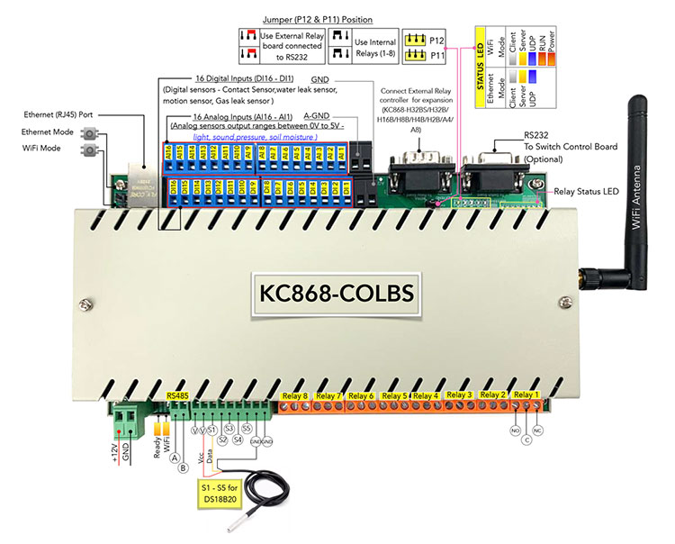
Led status different color means:
Red: Controller is power on.
Green: WiFi module is connect to your router successfully.
White: network run in “TCP Client” mode.
Yellow: network run in “TCP Server” mode.
Blue: network run in “UDP” mode. (Not used now)
what’s UDP , TCP Server, TCP Client means:
When set to “TCP Server”, controller own is a server work in local network ,you can use “KBOX” phone app without internet and our cloud server to control relay in local network.just your mobile phone or PC and controller connect with same router.
When set to “TCP Client” and set the server IP and port, controller will auto connect to your own server (not KinCony’s cloud server), you can write program for server and make your own phone app to use, this for developer to use.
what’s buttons function:
Button1 “WiFi Reset” : Reset WiFi module, then controller will be work as “AP” mode, you will see the wifi signal “LPT230” for use.Now you can config the ssid and password for your router.
Button2 “Ethernet Mode” : change ethernet work mode for UDP->TCP Server->TCP Client.
Button3 “WiFi Mode” : change WiFi work mode for UDP->TCP Server->TCP Client.
How to use buttons:
Button1 “WiFi Reset” : Hold on the button for 5 seconds,then restart power of controller.
Button2 “Ethernet Mode” :
Hold on the button until LED color changed. There are 5 status:
a.) Hold on button, when the [yellow LED] is ON, release it, then work mode in “TCP server” mode;
b.) Hold on button, when the [white LED] is ON, release it, then work mode in “TCP Client” mode;
c.) Hold on button, when the [blue LED] is ON, release it, then work mode in “UDP” mode; (Not use now)
d.) Hold on button, when the [yellow and white LED] all is ON, release it, then work mode in “UDP” and IP by DHCP mode;
e.) Hold on button, when the [yellow and white and blue LED] all is ON, release it, then work mode in “TCP Server” and IP (192.168.1.200) by static mode;
Note: after changed mode, the controller will restart automatically.
The controller default work mode is DHCP and TCP Server mode.
Button3 “WiFi Mode” :
Hold on the button until LED color changed. There are 3 status:
a.) Hold on button, when the [yellow LED] is ON, release it, then work mode in “TCP server” mode;
b.) Hold on button, when the [white LED] is ON, release it, then work mode in “TCP Client” mode;
c.) Hold on button, when the [blue LED] is ON, release it, then work mode in “UDP” mode; (Not used now)
Note: after changed mode, the controller will restart automatically.
The controller default work mode is DHCP and TCP Server mode.
2.Network Setting
A. use Ethernet port to config IP and different work mode and Wifi network setting
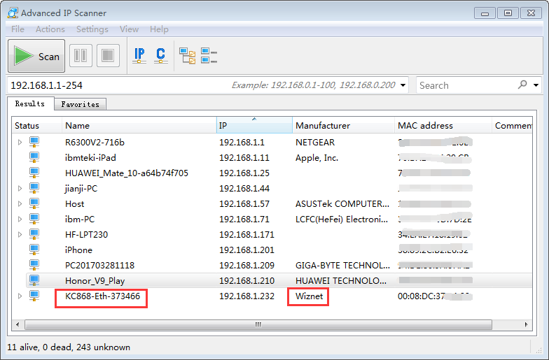
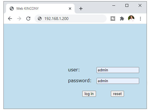
connect network cable with router, you can see the ethernet IP address or use other network IP scan software to find the controller’s ethernet IP. When you scan IP, you will find named “KC868-ETH-xxxxx” or “Wiznet” device, that’s our controller. Open browser, enter the IP, then you can open the config website. You can change work mode, different work mode function as same as WiFi’s. Login user name and password default is : admin admin
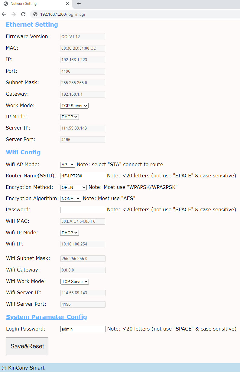
SSID and password: These are your router’s.
Work Mode:
1- TCP Server: Work in local network without internet, you can use PC application.
2- TCP Client: This mode for programmer or developer, controller can connect to your own cloud server by TCP socket connection.
2.How to use software
Firstly, use IP and Port connect to KC868-COLB logical controller.
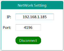
Input IP and Port
Connect/disconnect— PC Connect/disconnect with KC868-COL. All works need connect successfully firstly.
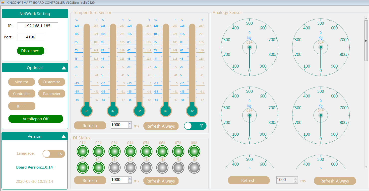
2.Optional
2.1 Monitor
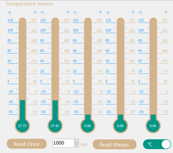
Temperature Sensor
Read 5 channels DS18B20 temperature sensors’ value, range(-55℃–125℃), ℃ is default unit, can change to ℉ to display.
[Refresh]:Read all temperature sensors for one time.
[Refresh Always]— Read all temperature sensors at regular time that you set. (100ms—3000ms)
DI Status
1#—16#— 16 channel Digital Input Channel
[Refresh]:Read all DI for one time.
[Refresh Always]— Read all DI at regular time that you set. (100ms—3000ms)
Analogy Sensor
1#—16#— 16 channel Analog Input Channel
[Refresh]:Read all AI for one time.
[Refresh Always]— Read all AI at regular time that you set. (100ms—3000ms)
Analogy Sensor Properity
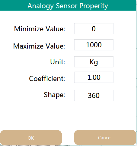
Double Click analog sensor dashboard can show [Analogy Sensor Properity]
(Range) Minimize Value: Actual physical range minimum value of input sensor
(Range) Maximize Value: Actual physical range maximum value of input sensor
Unit:Actual physical unit, Such as M/Pa/KG/V etc
coefficient:Defualt is 100,The formula of coefficient value is:(Maximize Value-Minimize Value)/5
[ For example,Water level sensor range is 0-10Meter, coefficient is (10-0) / 5=4 ]
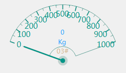
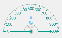
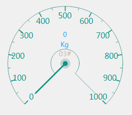
Shape (0-360):dashboard shape angle,default is 360 circular dashboard. For example , you can use 270,180,140 for different shaped dashboard.
2.2 Customize
Communication Transparent Transport
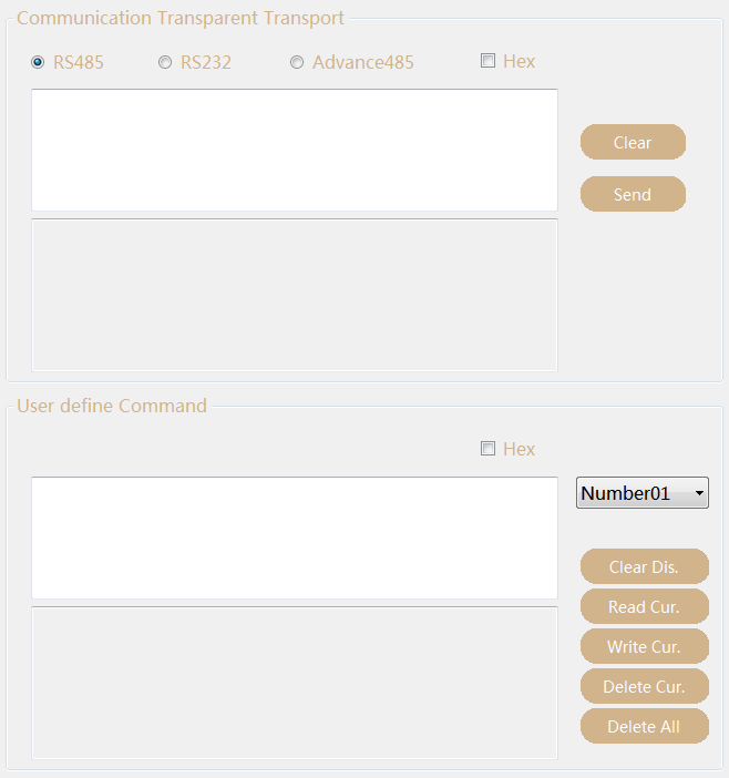
RS485– Edit command, send it by KC868-COL’s RS485 port, Communication baud rate is 9600bps.
RS232– Edit command, send it by KC868-COL’s RS232 port, Communication baud rate is 115200bps.
Hex— Check this option, will convert string command to HEX format, otherwise send command by AnsiString format.
Clear — Clear Edit content
Send — Send command to port that you have selected.
Mainly for debug and testing use.
User define Command
Create MAX 32 user define command line for ”IFTTT” use. “User define command” output to KC868-COL’s RS232 port.
Hex— Check this option, will convert string command to HEX format, otherwise send command by AnsiString format.
Chose “User define command” ID, then input command in edit area.
Clear Dis.– Clear edit area.
Read Cur.– Read selected ID of “User define command” from KC868-COL
Write Cur.– Write selected ID of “User define command” to KC868-COL
Delete Cur.– Delete selected ID of “User define command” in KC868-COL
Delete All.– Delete all ID of “User define command” in KC868-COL
2.3 Controller
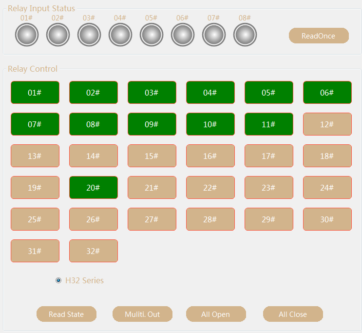
Relay Input Status—01#–08# input port of KC868-Hx controller
[ReadOnce]:Read input status of KC868-Hx controller for one time.
Relay Control—
[01#–32#]: 32 channel relay that connect with KC868-COL for manual control. Press ico, relay ON,color will be Green. Press ico, relay OFF, color will be Yellow.
[Read State]— Read controller’s relay status
[Multi.Out]— Right mouse button click relay ico, ico will dispaly “S” for select the relay, you can select for more relay channels, then press “Multi.Out” button for turn ON relays once time.
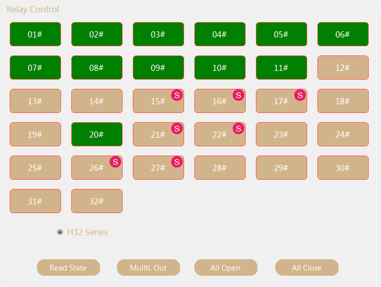
[All Open]—-Turn ON all relays
[All Close]—-Turn OFF all relays
Note:KC868-COL can connect with any controller of KC868-H32L,KC868-H16,KC868-H8,KC868-H4,KC868-H2 for different relay channel selected for automatic control system.
2.4 parameter
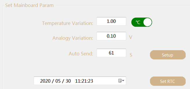
Set Main board Param
Temperature Variation: Report send message to PC when the temperature value change difference at variation value.
For example: when “Temperature Variation” is set to 1℃, if the second channel temperature rises from 25℃ to 26℃ or the temperature drops from 26℃ to 25℃, KC868-COL will automatically send the second channel temperature data to PC, and the monitor dashboard will refresh the new data value of the second channel temperature sensor (Note: need Enable the “Auto Report” function in the software homepage).
Analogy Variation: Report send message to PC when the analogy value change difference at variation value.
For example: when “Analogy Variation” is set to 0.1V, if the second channel rises from 2.5V to 2.6V or drops from 2.6V to 2.5V, KC868-COL will automatically send the second channel data to PC, and the monitor dashboard will refresh the new data value of the second channel sensor (Note: need Enable the “Auto Report” function in the software homepage).
Auto Send—-KC868-COL auto report to PC at a regular time for temperature and analogy sensor. (0–254second)
[Setup]— Write config to KC868-COL
Data and Time Setting— It’s display the KC868-COL’s system data and time.
[Set RTC]– Set the new date and time for KC868-COL
2.5 IFTTT
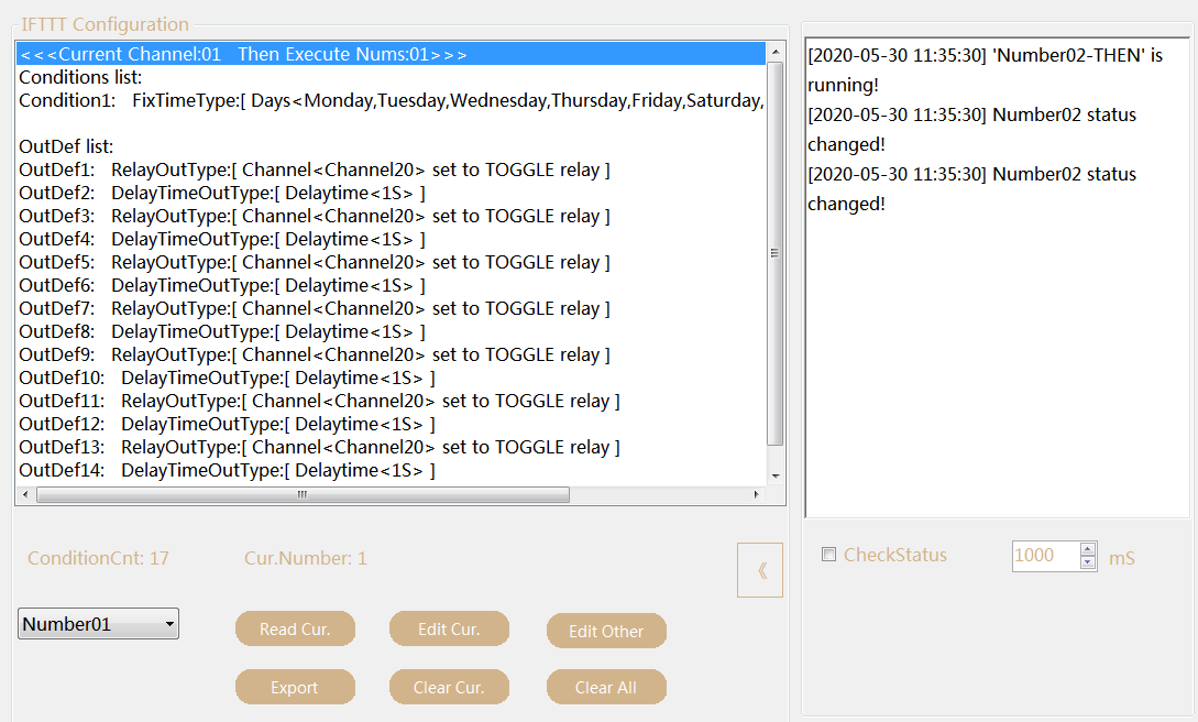
IFTTT Configuration— List IFTTT command details of selected ID
ConditionCnt— total count of IFTTT commmand have been created
Cur.Number—- Current Number of IFTTT command
Number**— IFTTT command ID , MAX 50 command
[Read Cur.]— -Read IFTTT command details that selected ID
[Edit Cur.]—- Edit IFTTT command that selected ID, after click will display IFTTT Setup window
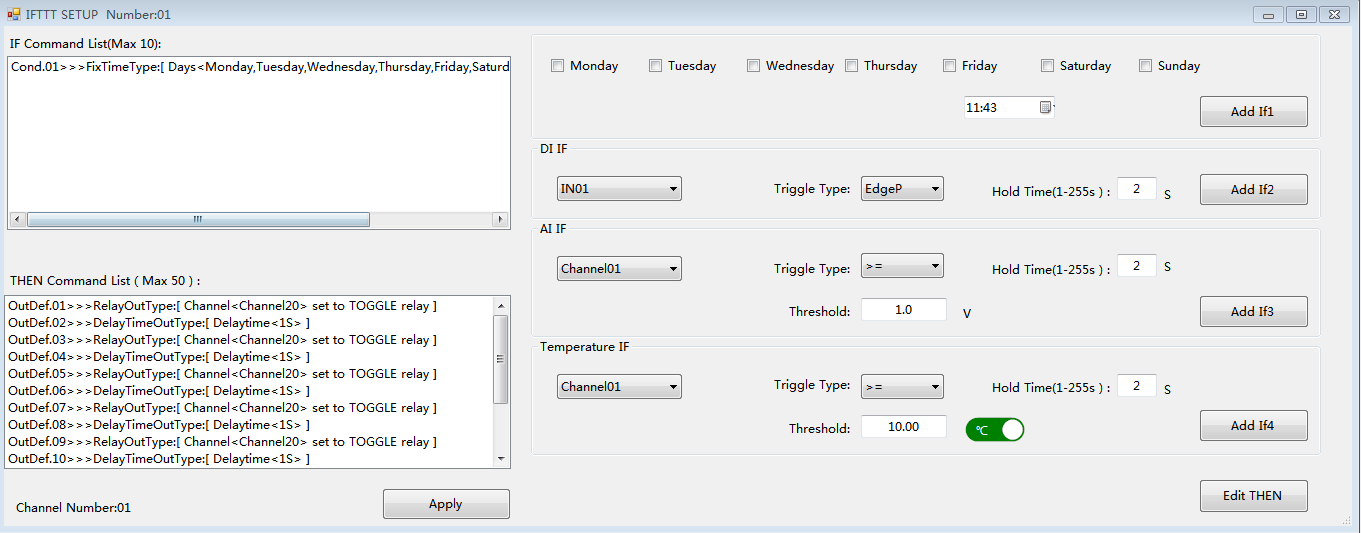
IF Command List (MAX 10 lines) — display have added if command
THEN Command List (Max 50)— display have added THEN command
Monday, Tuesday, Wednesday, Thursday, Friday, Saturday, Sunday—- Select week for IF command
[Add If1]—– add week IF condition to “IF Command List “
DI IF
IN01—IN16—-16 channel DI input ID
Trigger Type—Select the rising edge / falling edge trigger mode according to the type of sensor actually used
Hold Time(1-255s)— When the holding time of rising edge or falling edge reaches the preset value, the trigger is successful
[Add If2]—-add DI IF condition to “IF Command List “
AI IF
Channel01—Channel16—- 16 channel AI input ID
Trigger Type—Select comparison conditions for “>=” or “<” with threshold value
Hold Time(1-255s)—-When the holding time of analog sensor is greater than or less than the threshold value,the trigger is successful
threshold—- trigger value of analog sensor
[Add If3]—add AI IF condition to “IF Command List “
Temperature IF
Channel01—Channel05—- 5 channel temperature senor ID
Trigger Type—Select comparison Temperature for “>=” or “<” with threshold value
Hold Time(1-255s)—-When the holding time of temperature sensor is greater than or less than the threshold value,the trigger is successful
threshold—- trigger value of temperature
[Add If4]—add Temperature IF condition to “IF Command List “
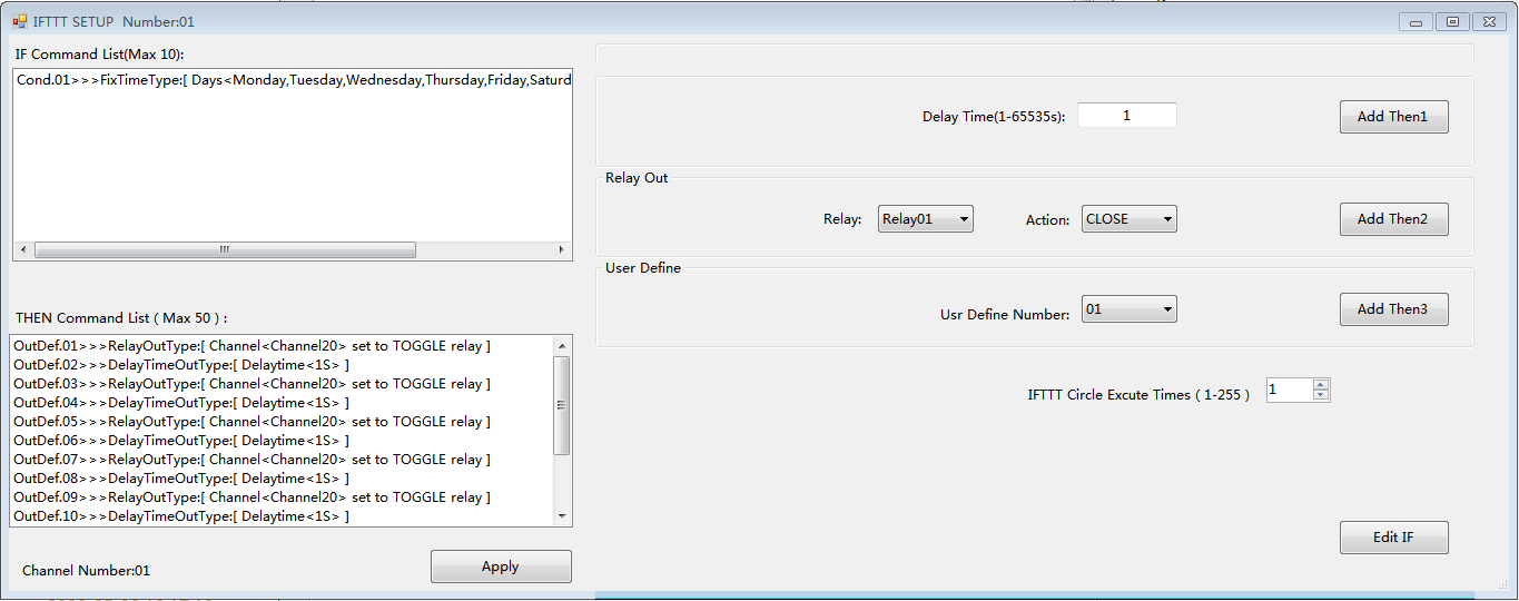
EDIT THEN
Delay Time(1-65535s)— Delay time for 1-65535 seconds can be set.
[Add Then1]—add Delay time action to “THEN Command List “
Relay Out
Relay— Chose relay ID
Action— CLOSE,OPEN,TOGGLE
CLOSE: Turn OFF relay of ID you have selected.
OPEN: Turn ON relay of ID you have selected.
TOGGLE: OFF->ON or ON->OFF relay of ID you have selected, just change relay status.
[Add Then2]—add relay action to “THEN Command List “
User Define
Usr Define Number— Select ID of user define command you have created in “Customize” function.
[Add Then3]—add user define action to “THEN Command List “
IFTTT Circle Excute Timers(1-255)— When the if condition is TRUE, how many times actions run.
[Apply]—after config IFTTT setting, write config to KC868-COL
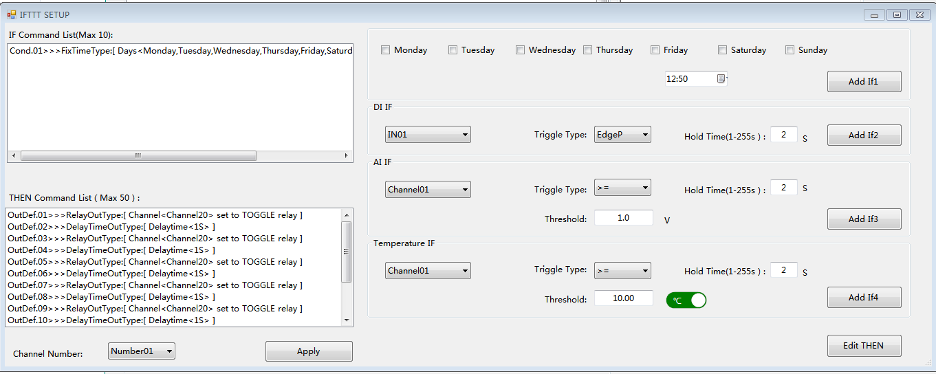
Edit Other
When Click “Edit Other” button on “IFTTT” window, also will go to edit window, the new window just can chose the IFTTT command ID number for edit.
Channel Number— you need chose channel number firstly, then begin to set “IF” and “THEN” command.
[Export]— export all IFTTT config information to folder “data”.
[Clear Cur.]— delete IFTTT command of selected ID from KC868-COL
[Clear All]— delete all IFTTT command from KC868-COL
Press “》” can open window for IFTTT running log information, use mouse right button can clear and copy to clipboard.
Check Status option— use for search for KC868-COL at a regular time, not check is better.
3.Version
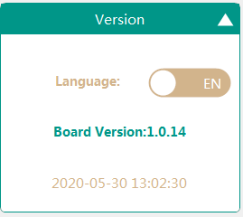
Language—chose language for Chinese or English
Board Version—KC868-COL firmware version
- How to change software language to your own language
You can modifiy “ui.ini” File content, rename menus and device names by your own languages for different countries to use.

[/vc_column_text][/vc_column][/vc_row]
