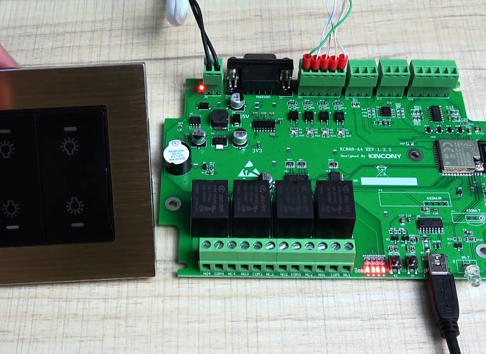
We continue the ultimate guide to the Kincony KC868-A4 controller, which began in the previous article. Today we will analyze in detail the pinout of the KC868-A4 and get acquainted with the principles of programming the components (functional blocks) of this controller. All examples will be accompanied by ready-made working code that you can use in your projects.We will start with the pinout of the central ESP32-S module and analyze what and how is connected to it by Kincony engineers.
▍ Pinout KC868-A4
The ESP32 microcontroller is good for everyone, but it has one inherent drawback – an extremely small number of free GPIO contacts. And everyone who wants to design a controller on ESP32 or at least just use it in his more or less developed project, is forced to somehow solve this problem. You have to either use port extenders, or try to somehow “accommodate the unattended” and try to distribute the available GPIO in crumbs and abandon certain components that could be installed on the board. in their opinion, the most popular components (functional blocks), which included:
- 4 digital inputs
- 4 analog inputs
- 2 analog outputs
- 4 relays
- Temperature/humidity sensor(s)
- RS232 interface
- RF Module 433 MHz
- Infra red (IR) module
- Buzzer
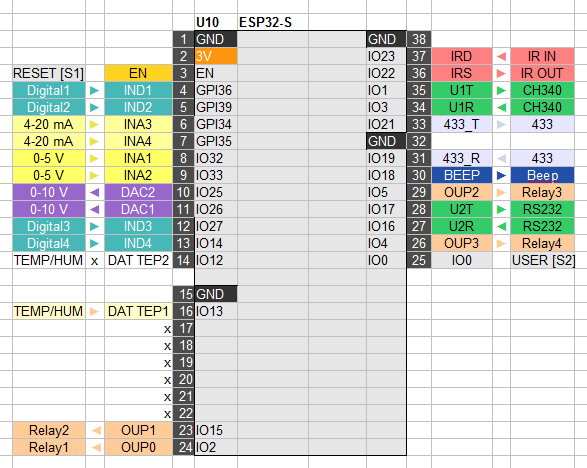
This set took all the free GPIO of the ESP32 controller, there is not a single pin left to which you could connect something of your own. But looking at what Kincony engineers have installed on the KC868-A4 board, you can say that they have a fairly balanced solution for small projects and the purpose of learning to program microcontrollers. The problem is that if you want to connect some of your part or module to the KC868-A4, then without a soldering iron and the appropriate qualifications, you will not succeed – there are simply no GPIO free to connect. On the other hand, the ideology of such controllers does not provide for such liberties on the part of users – you buy a ready-made solution and just use the set of features that it provides. So, below is an essay by Kincony engineers on the topic “How I distributed GPIO esp32 contacts”, recorded by me in the form of a table. In the columns closest to the controller, the lines and connection designations from the circuit diagram are indicated (see the previous article), and in the far ones – the inputs and outputs of the functional blocks of the KC868-A4 controller. In general, not bad, the main advantage of such a GPIO layout I would call the fact that all this really works and does not interfere with each other. If I were engaged in the design of Kincony KC868-A4, then I would first of all get rid of connecting wireless modules at 433 MHz, as archaic, in favor of something more modern, such as nRF24 or LoRa, would output contacts for connecting equipment via I2C and SPI and hang digital inputs/outputs on port extenders. And also added a block of real-time clocks and brought the relay unit into a separate module on the DIN-rail. But then it would be a completely different controller, so let’s go down from heaven to earth and continue the analysis of Kincony KC868-A4. With the distribution of GPIO contacts ESP32, everything is more or less clear and now, armed with this information, let’s start actually programming the individual functional blocks of Kincony KC868-A4 and we will start with the software environment.
▍ Software environment for KC868-A4
You can program the Kincony KC868-A4 controller in any environment that suits you—you can use your favorite IDE to do so, but I’ll give examples for Arduino 1.8.5. It is assumed that you have the necessary qualifications and are familiar with working in the Arduino IDE and know how to program the ESP32 microcontroller. To work with Kincony KC868-A4, from the entire list of supported controllers you need to select the option “NodeMCU-32S”. This transparently hints that the Kincony KC868-A4 is an enhanced and peripheralized version of nodeMCU-32S.
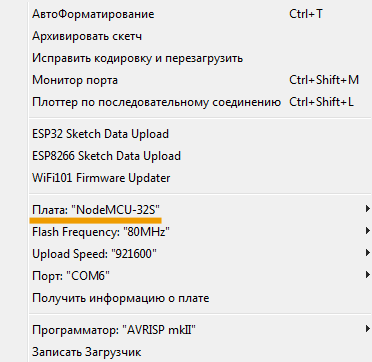
The rest of the settings are visible in the screenshot, you need to set the same (except for the port number, which you will have your own). Now let’s proceed to the analysis of the examples of programming the functional blocks of the Kincony KC868-A4 controller.
▍ Program the relay KC868-A4
Of course, we will start with relay control, as with the simplest and most popular functionality of such controllers. The relays, as can be seen in the above pinout diagram, are connected to GPIO 2, 15, 5, 4. For an example of relay control of the Kincony KC868-A4 controller, we will create a sketch that switches the relay in turn, creating the effect of “running fire”.
/*
Kincony KC868-A4
Relays example
*/
byte pins[] = {2, 15, 5, 4};
byte pos = 0;
void setup() {
Serial.begin(115200);
Serial.println(F(“Start Kincony KC868-A4 Relays example…”));
pinMode(pins[0], OUTPUT);
pinMode(pins[1], OUTPUT);
pinMode(pins[2], OUTPUT);
pinMode(pins[3], OUTPUT);
}
void clear() {
digitalWrite(pins[0], LOW);
digitalWrite(pins[1], LOW);
digitalWrite(pins[2], LOW);
digitalWrite(pins[3], LOW);
}
void change(byte n) {
clear();
digitalWrite(pins[n], HIGH);
}
void loop() {
change(pos);
Serial.print(F(“ON Relay #”)); Serial.println(pos);
delay(10000);
pos++;
if (pos > 3) {pos = 0;}
}
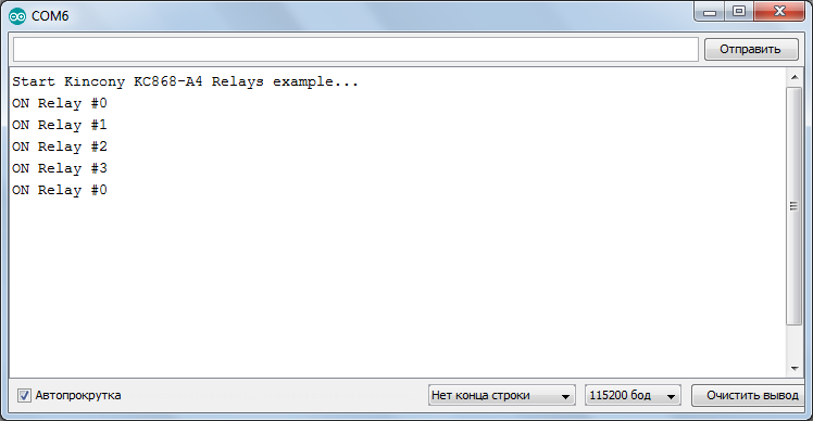
This example is enough for you to use it to implement any relay control logic of the Kincony KC868-A4 controller. Here is the output in Serial of our test sketch:
▍ Buzzer and tone
As I noted earlier, the Kincony KC868-A4 board is equipped with a nice addition in the form of a piezoelectric emitter. It can help you make a convenient sound alert about various states (crash, some events, etc.) of the controller. Here’s a simple example of working with a squeaker.
/*
Kincony KC868-A4
Buzzer example
*/
#define BUZZER_PIN 18
void setup() {
Serial.begin(115200);
Serial.println(F(“Start Kincony KC868-A4 Buzzer example…”));
pinMode(BUZZER_PIN, OUTPUT);
}
void loop() {
digitalWrite(BUZZER_PIN, HIGH); delay(500);
digitalWrite(BUZZER_PIN, LOW); delay(500);
}
The above example is enough to simply draw attention to the controller when an event occurs, but if you use the tone of the sound, you can distinguish each type of event with its own separate sound (melody). Here’s an example of using different tones when alerting.
/*
Kincony KC868-A4
Buzzer Tone example
*/
#define BUZZER_PIN 18
const int TONE_PWM_CHANNEL = 0;
void setup() {
Serial.begin(115200);
Serial.println(F(“Start Kincony KC868-A4 Buzzer Tone example…”));
ledcAttachPin(BUZZER_PIN, TONE_PWM_CHANNEL);
}
void loop() {
ledcWriteNote(TONE_PWM_CHANNEL, NOTE_C, 4); delay(500);
ledcWriteNote(TONE_PWM_CHANNEL, NOTE_D, 4); delay(500);
ledcWriteNote(TONE_PWM_CHANNEL, NOTE_E, 4); delay(500);
ledcWriteNote(TONE_PWM_CHANNEL, NOTE_F, 4); delay(500);
ledcWriteNote(TONE_PWM_CHANNEL, NOTE_G, 4); delay(500);
ledcWriteNote(TONE_PWM_CHANNEL, NOTE_A, 4); delay(500);
ledcWriteNote(TONE_PWM_CHANNEL, NOTE_B, 4); delay(500);
ledcWriteNote(TONE_PWM_CHANNEL, NOTE_C, 5); delay(500);
}
▍ DAC
Kincony KC868-A4 is equipped with two digital-to-analog converters (DAC), which can generate voltages in the range from 0 to 10 volts. This can be useful for controlling various equipment. Below is an example of the generation of a dc voltage of 5 volts at the output of the DAC1 controller.
/*
Kincony KC868-A4
DAC example
*/
#define DAC1 26
#define DAC2 25
void setup() {
Serial.begin(115200);
Serial.println(F(“Start Kincony KC868-A4 DAC example…”));
int value = 127; // 255 = 10V
dacWrite(DAC1, value);
}
void loop() {
}
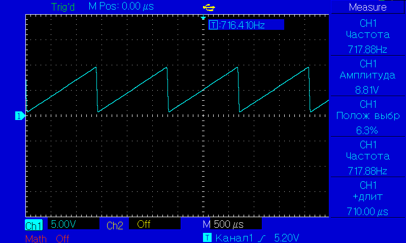
It is clear that dc voltage generation is only a small area of application of DAC, mainly dynamic generation of (periodic) signals is in demand. Next, you can see a code example to generate a sawtooth signal at the output of DAC1.
/*
Kincony KC868-A4
DAC Saw example
*/
#define DAC1 26
#define DAC2 25
byte value = 0;
void setup() {
Serial.begin(115200);
Serial.println(F(“Start Kincony KC868-A4 DAC Saw example…”));
}
void saw() {
value++;
}
void loop() {
dacWrite(DAC1, value);
saw();
}
With a small modification of this code, you can achieve signal generation from the Kincony KC868-A4 controller of almost any shape.
▍ Digital inputs
The Kincony KC868-A4 controller has 4 digital dry contact inputs that are connected to GPIO 36, 39, 27 and 14. Maintenance of these inputs is extremely simple and is carried out by almost one digitalRead() function – you get the current state of any of the controller inputs and then use it in the code as you see fit.
/*
Kincony KC868-A4
Digital Input example
*/
#define INPUT_PIN1 36
#define INPUT_PIN2 39
#define INPUT_PIN3 27
#define INPUT_PIN4 14
void setup() {
Serial.begin(115200);
Serial.println(F(“Start Kincony KC868-A4 Digital Input example…”));
pinMode(INPUT_PIN1, INPUT);
}
void loop() {
Serial.println(digitalRead(INPUT_PIN1));
delay(10);
}
▍ Analog inputs
Kincony KC868-A4 has 4 “analog” inputs that are connected to GPIO 32, 33, 34 and 35. As noted in the first article, the input stages for signals 0-5 V and 4-20 mA are formed, which form 2 inputs for voltage (GPIO 32 and 33) and 2 inputs for current (GPI 34 and 35). In the code, the work with both types of input signals is not different, it is implemented by the analogRead() function with a resolution of 4096.
/*
Kincony KC868-A4
Analog Input example
*/
#define ANALOG_PIN1 32 // INA1 0-5V
#define ANALOG_PIN2 33 // INA2 0-5V
#define ANALOG_PIN3 34 // INA3 4-20 mA
#define ANALOG_PIN4 35 // INA4 4-20 mA
int value1 = 0;
void setup() {
Serial.begin(115200);
Serial.println(F(“Start Kincony KC868-A4 Analog Input example…”));
pinMode(ANALOG_PIN1, INPUT);
}
void loop() {
value1 = analogRead(ANALOG_PIN1); // 0-4096
delay(1000);
Serial.printf(“Value on pin %d = %d\n”, ANALOG_PIN1, value1);
}
▍ Temperature and moisture sensors
Kincony KC868-A4 has a 3V, S, GND pad for connecting the DS18B20 temperature sensor. You can also connect a network of several DS18B20 sensors, a humidity sensor or any other sensor suitable for the type of connection to this module. You just need to remember that the board already has a data line lift to the power supply voltage. To work with the DS18B20 temperature sensors,
the DS18B20 and OneWire libraries are required . Below is the code for one DS18B20 sensor connected to the KC868-A4 board.
/*
Kincony KC868-A4
DS18B20 example
*/
#include <DS18B20.h>
#define LOW_ALARM 30
#define HIGH_ALARM 40
DS18B20 ds(13);
void setup() {
Serial.begin(115200);
Serial.println(F(“Start Kincony KC868-A4 DS18B20 example…”));
ds.doConversion();
while (ds.selectNext()) {
ds.setAlarms(LOW_ALARM, HIGH_ALARM);
}
}
void loop() {
ds.doConversion();
while (ds.selectNextAlarm()) {
Serial.print(“Alarm Low: “); Serial.print(ds.getAlarmLow()); Serial.println(” °C”);
Serial.print(“Alarm High: “); Serial.print(ds.getAlarmHigh()); Serial.println(” °C”);
Serial.print(“Temperature: “); Serial.print(ds.getTempC()); Serial.println(” °C\n”);
}
delay(2000);
}
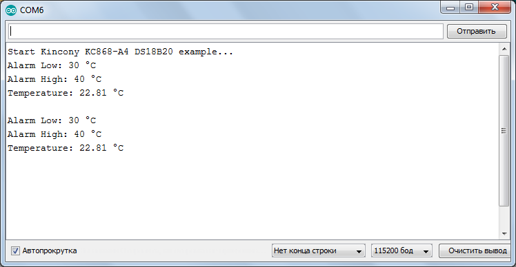
The code sets trigger thresholds and, if the controlled temperature goes beyond certain values, serial displays a corresponding message. The DS18B20 library contains many examples of using the DS18B20 temperature sensors for all occasions – you can easily use them for your projects.
▍ 433 MHz receiver and transmitter
As you already know, the Kincony KC868-A4 controller includes 433 MHz receiver and transmitter modules. These modules can be used to control various equipment and receive data from sensors that use the 433 MHz band to transmit their signals. The receiver is connected to
the GPIO 19 of the controller, and the transmitter to the GPIO 21. To work with wireless transmission and data reception, the popular RC-Switch library is used. Here is an example of sending data and control commands to a wireless module on 433 MHz of the Kincony KC868-A4 controller.
/*
Kincony KC868-A4
433 Transmit example
*/
#include <RCSwitch.h>
RCSwitch mySwitch = RCSwitch();
#define DELAY_MS 500
void setup() {
Serial.begin(115200);
Serial.println(F(“Start Kincony KC868-A4 433 Transmit example…”));
mySwitch.enableTransmit(digitalPinToInterrupt(21));
}
void loop() {
mySwitch.switchOn (“11111”, “00010”); delay(DELAY_MS);
mySwitch.switchOff(“11111”, “00010”); delay(DELAY_MS);
mySwitch.send(5393, 24); delay(DELAY_MS);
mySwitch.send(“000000000001010100010001”); delay(DELAY_MS);
mySwitch.sendTriState(“00000FFF0F0F”); delay(DELAY_MS);
}
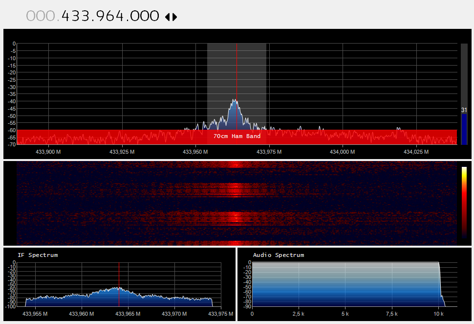
Visual visualization of the work of this sketch in the program SDRSharp. You can see the sending of data to the air by the controller every 500 milliseconds.Similarly, you can use examples of receiving (GPIO 19) signals in the 433 MHz band, which are part of the RC-Switch library.
▍ Infrared (IR) receiver and transmitter
We will complete the overview of the Kincony KC868-A4 software modules with an example of working with a receiver (GPIO 23, IRD) and an emitter (GPIO 22, IRS) of infrared signals. Using this receiver and transmitter, you can organize control of any equipment that uses infrared remotes for their work. You can both record codes from your control panels and issue them (codes) to the air to control your equipment.To work with an infrared receiver and The transmitter uses the
Arduino-IRremote library. Consider an example based on it. In this test sketch, we will receive an infrared signal from a household control panel, identify this signal (hardware manufacturer, signal frequency, control protocol, and key code), and send the recorded signal to the air by pressing the function key of the Kincony KC868-A4 controller. Initial data:
- IR receive: GPIO 23
- IR send: GPIO 22
- Function button: GPIO 0
- STATUS_PIN is used in the sketch to indicate events, but since the Kincony KC868-A4 uses almost all GPIO ESP32 (and GPIO2 is also occupied), the built-in LED (D2) is redesigned to the (conditionally) free pin D12.
The complete sketch code contains 2 files: the main file (ir_example.ino) and the settings file (PinDefinitionsAndMore.h). In the PinDefinitionsAndMore.h file, you need to change the GPIO numbers to match the pinout of the Kincony KC868-A4 controller (the settings strings are marked with three exclamation points).
#define LED_BUILTIN 12 // !!!
#define IR_RECEIVE_PIN 23 // !!!
#define IR_SEND_PIN 22 // !!!
#define APPLICATION_PIN 0 // !!!
The complete code of the PinDefinitionsAndMore.h file
The complete code of the ir_example.ino file
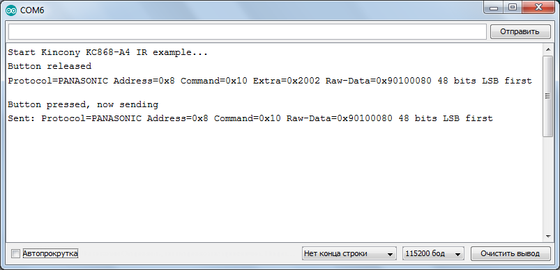
The result of the sketch: first, we receive the IR signal from the remote and decode it, and then send it to the air (duplicate) by pressing the “USER” button of the Kincony KC868-A4 controller.
▍ Conclusion
In the second article of the series, we looked at “atomic” examples of programming various functional blocks of the Kincony KC868-A4 controller. Using this information, you can easily start programming the controller for your tasks – everything is painted “from and to”: photos, diagrams, pinout, code examples, links to libraries, screenshots, explanations, etc. In the next article, we will look at more complex examples of working with the KC868-A4, such as working with the wireless Wi-Fi part and remote control of the controller via the Internet using Telegram and / or Whatsapp messengers.


