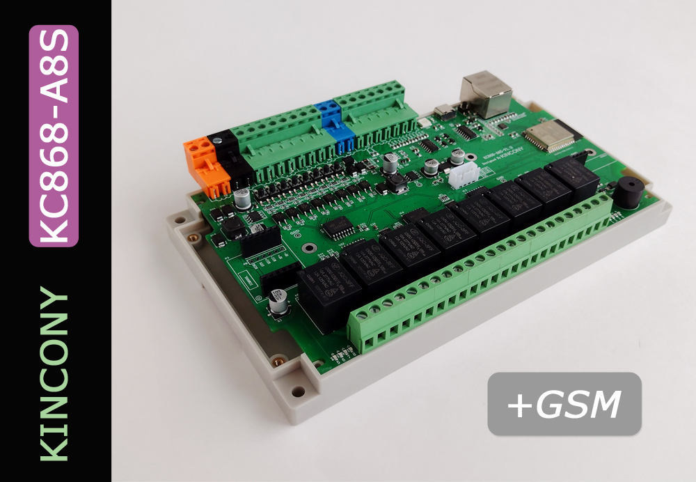
The controller Kincony KC868-A8S, an upgraded version of the previously considered controller KC868-A8, is on the table today. Upgraded so much that in fact it is already a completely different controller with much wider features, the main of which is the possibility of working in GSM networks. Developers and programmers Kincony KC868-A8S have done their best to develop a device that allows (simultaneous) communication over Wi-Fi, Ethernet, Bluetooth, 433 MHz, RS485 and GSM, receive, send and redistribute various IoT data and commands. This is a controller to my liking, when you can’t deny yourself anything and use any interfaces (and their combinations) to freely design your system’s IoT architecture. Let’s see in more detail what else is in the Kincony KC868-A8S model and what else will delight us …
Kincony KC868-A8S
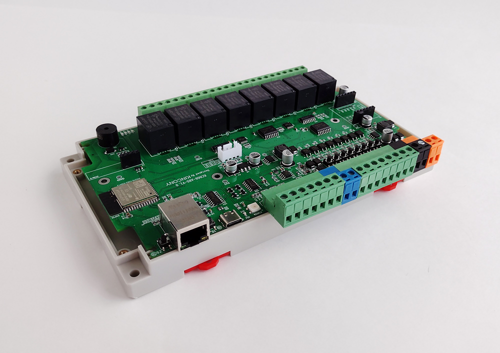
The difference between KC868-A8 and KC868-A8S is noticeable to the naked eye – controllers differ even in the overall dimensions: the A8S is much larger and involves installation in the wider case on the DIN rail. In the upgraded model there were LEDs for marking the status of digital inputs, input test buttons, the number of analog inputs increased to 4, the RS485 connection, the connection of the GSM module, the piezoceramic speaker (Buzzer), the RGB LED WS2812 and the USB Type-C program connector appeared.
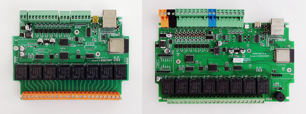
A8 and A8S for comparison
But we also have some (minor) losses, we can note the loss of the connector for connecting the transmitter module to 433 MHz and a decrease from 4 to 1 connector for connecting external sensors. What can be sacrificed in this situation. The KC868-A8S panel contains:
- ESP32 (ESP-WROOM-32)
- 8 digital opto-insulated inputs (“dry contact”)
- 8 digital entry status LEDs
- 8 digital input test buttons
- 4 analog inputs 0-5 V
- 8 relays 10A 220V (NO, COM, NC)
- 8 relay status LEDs
- 1 connector for connecting temperature and other sensors
- RS485 port
- 433 MHz receiver connector
- GSM Module Connectivity Connector
- Ethernet LAN8270A
- Piezoceramic speaker
- RGB LED WS2812
- I2C connector
- USB Type-C
- Reset button and program button
- Power connector 12 V
A very impressive set, now a little more detail about individual innovations:
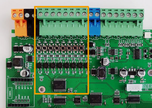
LEDs and digital input buttons. A nice addition to the functionality of the controller is always clear in what state the entrances are in and with the help of buttons you can quickly test the operation of these inputs.
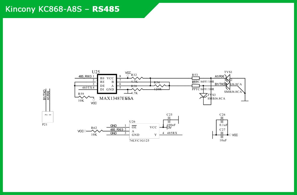
RS485 interface. A very useful acquisition, for the RS485 interface does not need a special introduction and recommendations.
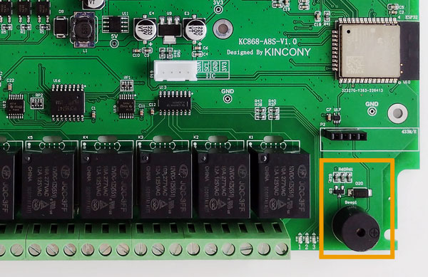
Piezoceramic speaker (Buzzer). As they say, a trifle, but beautiful. Buzzer can notify about various situations, including emergencies.
RGB LED WS2812. If not have display, then at least a multi-color LED, which can also notify about various events and states of the system.
USB Type-C. Usb Type-C is used, the company Kincony follows the moderne trende.
GSM module. This is a “feature” of this controller, which really greatly expands the capabilities of KC868-A8S – it becomes possible to control the SMS system using and work “bypass” traditional Wi-Fi and Ethernet (for example, when there is no WiFi signal or are turned off ) the GSM can continue to communicate. Together with the existing functionality of A8, A8S plugins make the controller a very powerful tool for realizing your needs in ioT projects.
Layout and device
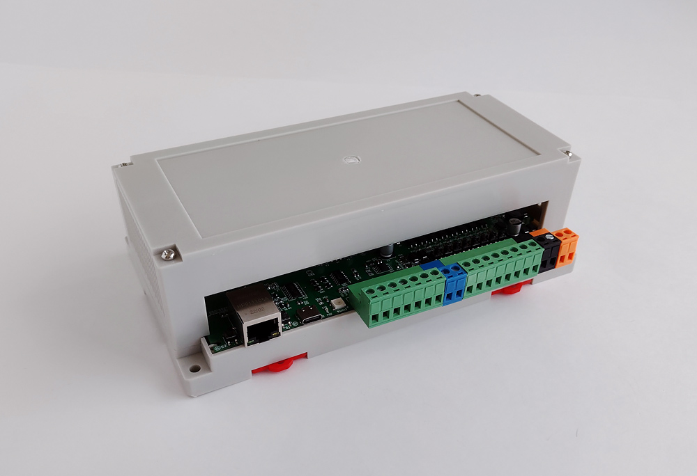
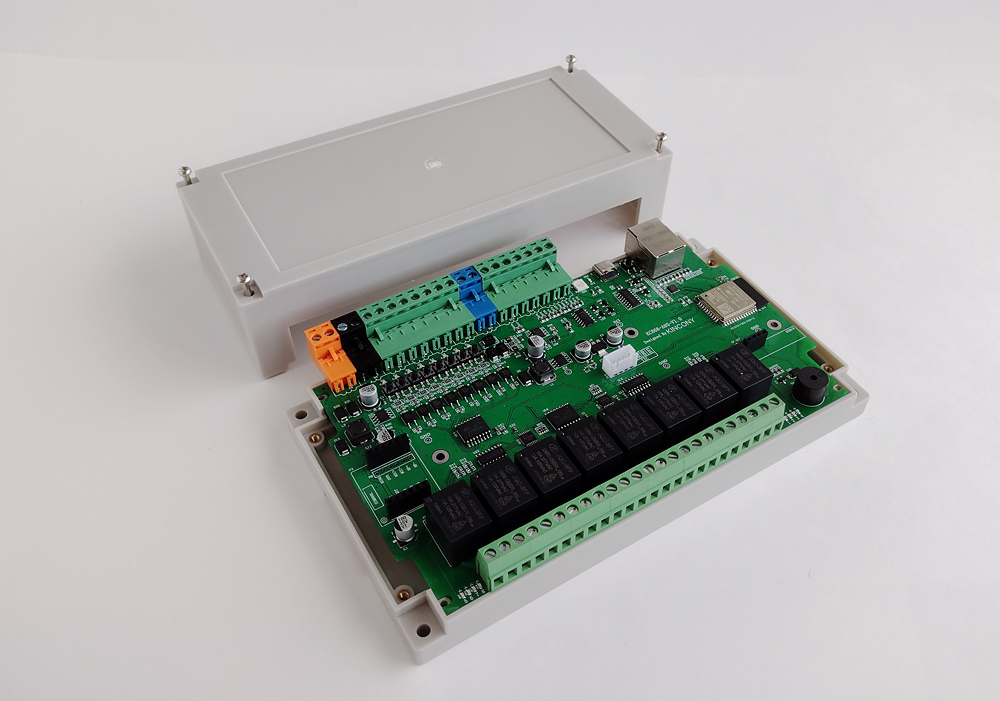
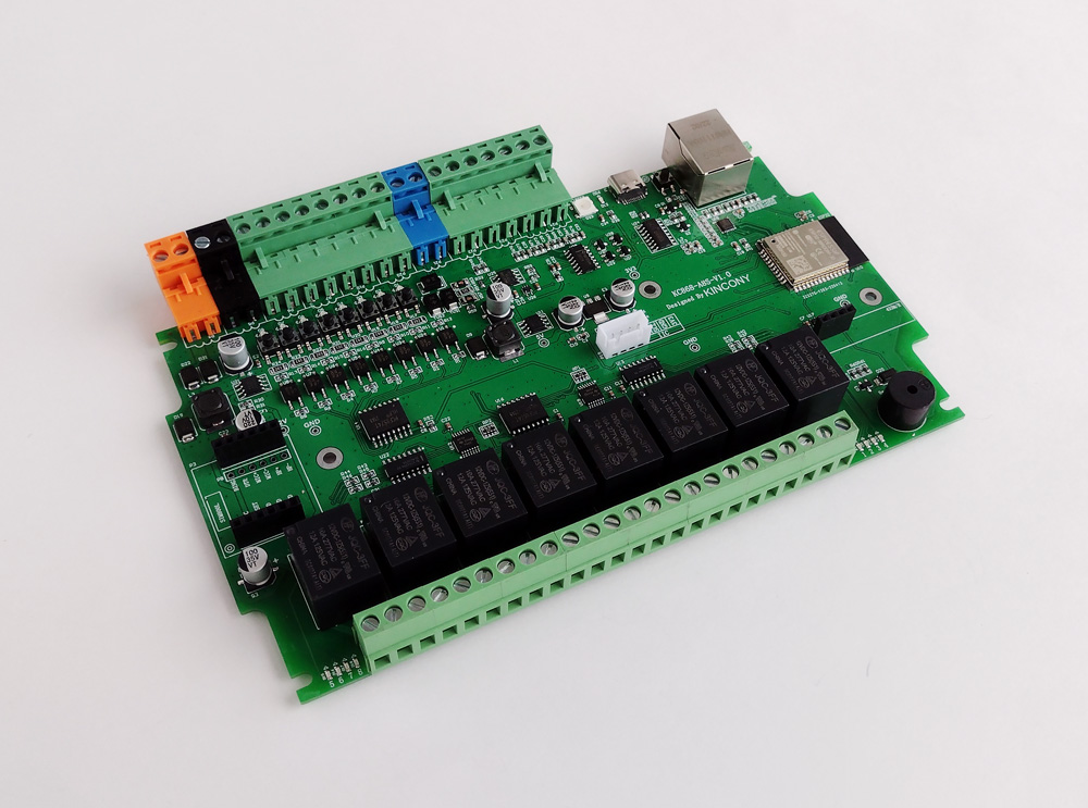
The controller is installed in the extended version of the case on the DIN rail. In general, it is not bad, although the standard (short) version of the case would be more convenient – in the top cover there are holes for the installation of the display and for additional external connectors. The quality of plastic and its casting with this controller is somewhat better than before. Here everything is simpler – in front of us is a modest “workhorse” made of gray plastic of 4+ quality (but not 5). Although the functional housing is made perfectly – it has the correct geometry, reinforced metal holes for screws, everything is combined, disassembled and assembled very simply and without any effort. View of the controller from the back – you can see the connections of digital and analog inputs, the connector for connecting the external sensor, the RS485 and Ethernet interfaces, as well as the mounting plates for attaching the controller to the DIN rail (red at the bottom). The KC868-A8S panel is a separatea.
Motherboard
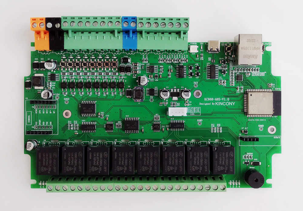
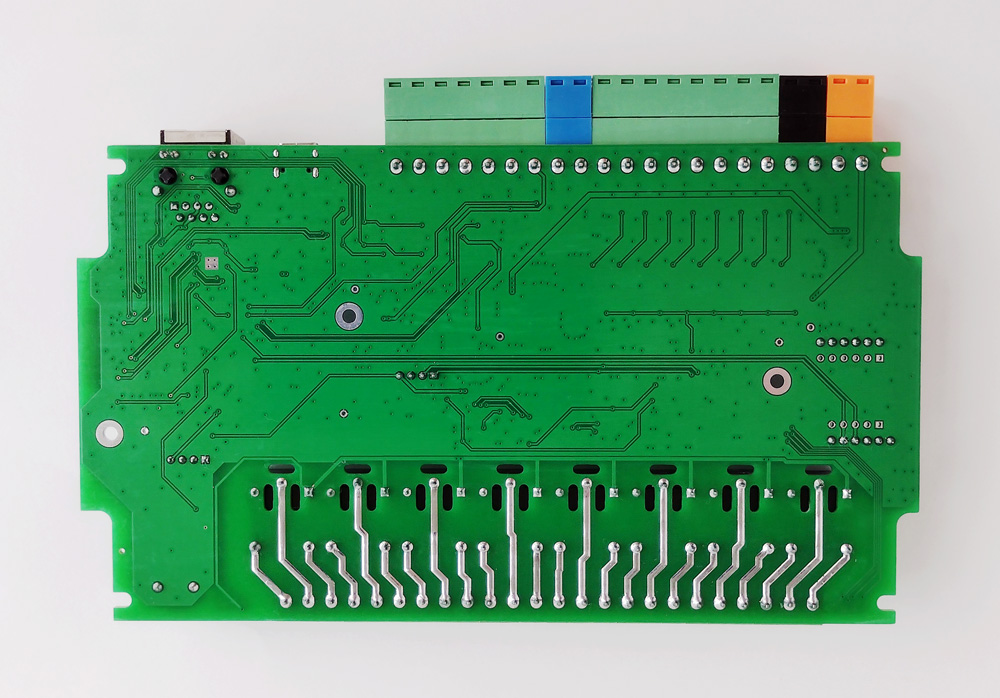
Now let’s move on to getting acquainted more closely with the KC868-A8S and analyzing the assemblies of this controller. First, the view from above. Pay attention to the revision of my sample (V1.0), now new and slightly modernized revisions are already being published, we will talk about it in more detail a little below. Traditionally, most Kincony controllers have installed elements only on the upper side of the board. KC868-A8S is no exception in this regard – the underside of the board is intact.
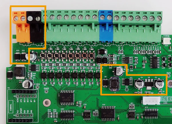
Voltage power supply
Standard for the KC868 series energy subsystem version: the chip step-down DC-DC converter XL1509-5 is used to form a voltage of 12 V and 5 V, and the linear controller LM117-3V3 for generating a voltage of 3.3 V KC868-A8S we see another innovation – +12 V and GND connectors are made double. Personally, I like this little upgrade. The panel also has an LED. Dijagram power supply of the KC868-A8S power subsystem:

ESP32 Core
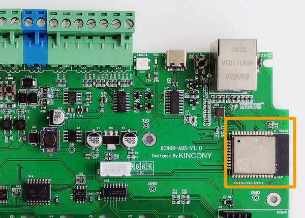
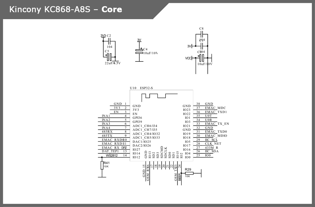
Here everything is standard – a place on the board of the ESP-WROOM-32 module and its binding, which have already become classic for the KC868 series. Schematic diagram and pinout core of the ESP32 controller:
USB/CH340
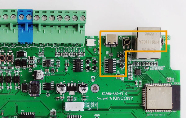
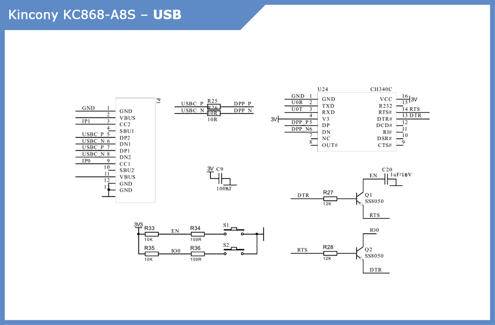
Subsystem for connecting to your computer and programming controllers. The mini-USB connector was replaced by a more modern Type-C, followed by CH340C and two buttons – “RESET” and “USER” (“DOWNLOAD”). Schematic diagram of the USB/CH340 controller subsystem:
Digital Inputs (DI)
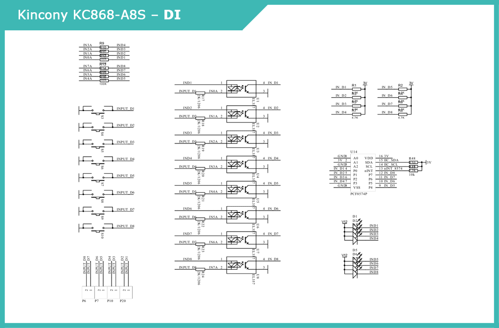
The KC868-A8S has 8 digital opto insulated inputs on EL357 optocouplers. Interaction with ESP32 deals with the expansion of digital inputs/outputs with the I2C interface PCF8574P, which saves a meager GPIO, although it worsens the performance of the KC868-A8S input and somewhat complicates programming. Here we see the added LED indicator and input test buttons. Schematic diagram of the digital input subsystem:
Analog Inputs (AI)
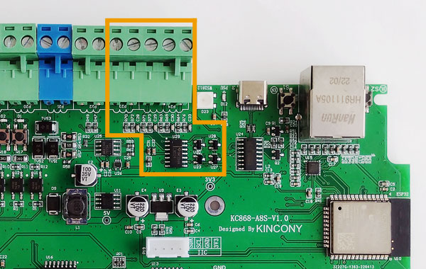
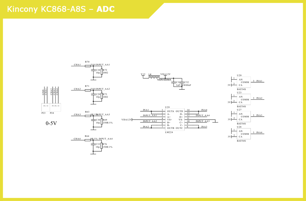
The KC868-A8S has 4 analog inputs of 0–5 V. Signals are generated by input stages, quadruple operational amplifier LM224 and SCHOTTKY BAT54S diodes. Here you need to pay attention to one remark: at my disposal is the model KC868-A8S revision 1.0 and has 4 analog inputs 0-10 V. On the manufacturer’s website in the specifications there are 2 analog inputs 0-10 V and 2 inputs 4-20 mA. VCC_12V_1 Perhaps in the new revisions of the controller, the input circuits of analog inputs have been changed and their configuration has changed – pay attention to this observation when ordering this controller. Schematic diagram of the analogue input subsystem:
Relays
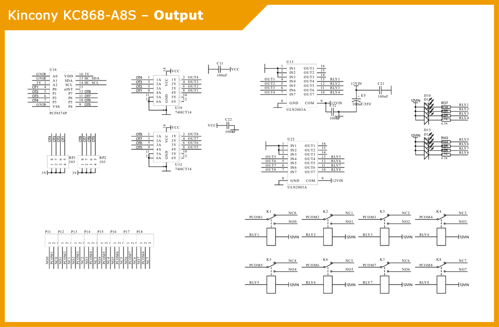
The 8 relays service two 74HCT14 chips with Inverting Schmitt triggers and two ULN2003A chips with Darlington transistor arrays. On the board there are indicator LEDs that signal the current state of the relay. Interaction with the ESP32 microcontroller is carried out using a digital input/output extension with the I2C interface PCF8574P. Relays have 3 contacts (NO, COM, NC), which allows you to fully use them in various load on/ off schemes. Schematic diagram of the relay subsystem:

Sensor (temperature/humidity)
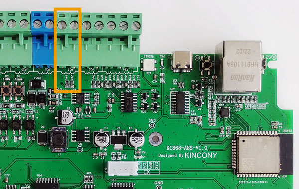
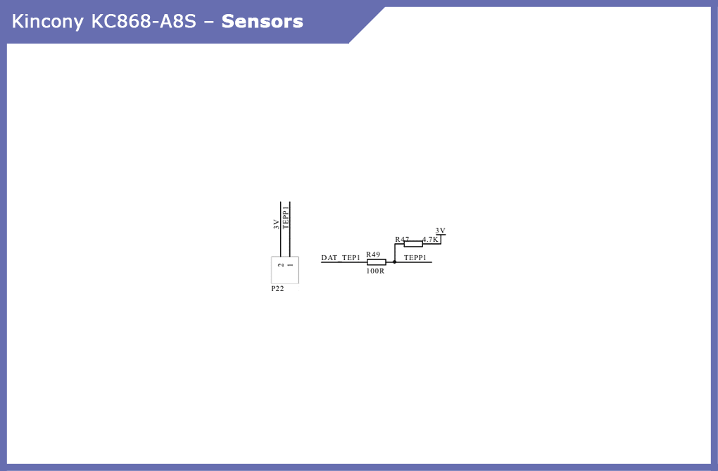
The KC868-A8S has 1 connector for connecting the temperature or other sensors (you can connect any suitable sensors or networks of several sensors, you just need to remember that the contact pulls it already on the board at a voltage of 3 V). In extreme cases, you can remove the restriction resistor from the board and get a “clean” GPIO, to which you can connect the necessary equipment.
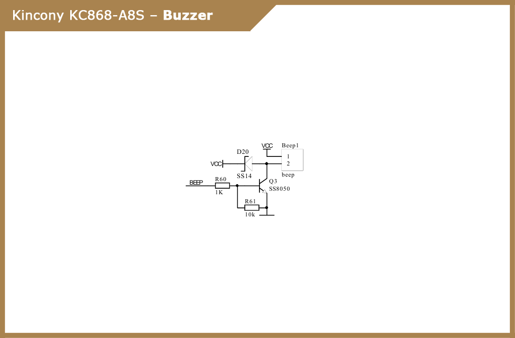
Buzzer
A big thank you to Kincony for the buzzer on the board, with it working with the controller will be much more “fun” and interactive. For example, if something goes wrong, you can notify the user about it with permanent buzzer thrillers.
433 MHz
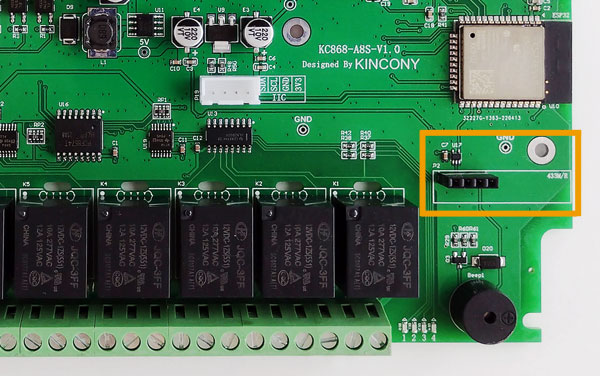
Here we see a connector for connecting the receiving module to 433 MHz. The loss of the transmitter in this model is clearly due to the lack of a free GPIO on esp32. Here we have a certain freedom of action: if necessary, you can try to connect the 433 MHz transmitter module to the KC868-A8S or vice versa, use a 433 MHz port to connect the equipment of some third party.

Ethernet
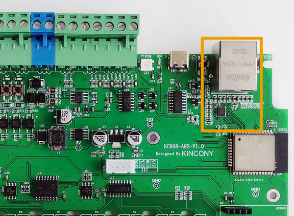
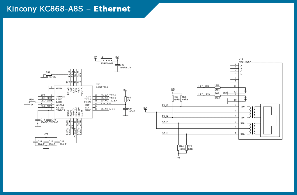
In KC868-A8 Ethernet was a “chip”, in KC868-A8S it is a standard option, but it still allows you to connect the controller via Wi-Fi, or Ethernet, or at the same time to interface two, or use another interface as a backup, etc. Schematic diagram of the Ethernet subsystem interfacee:
RS485
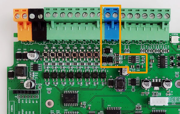
KC868-A8 had no support for the RS485 interface, KC868-A8S eliminated this unfortunate flaw: developers added RS485 to the board. This subsystem provides a MAX13487EESA driver and a 74LVC1G125 buffer. Schematic diagram of the RS485 interface subsystem:
I2C
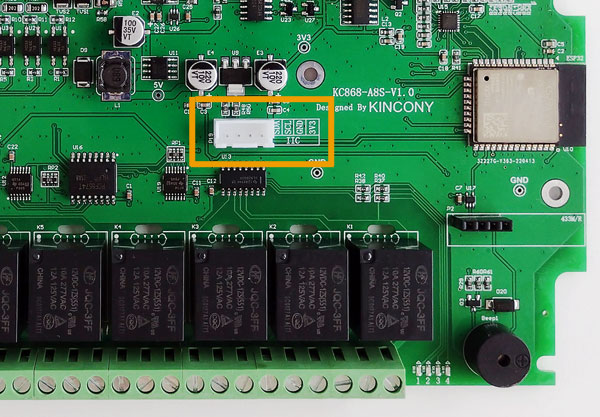
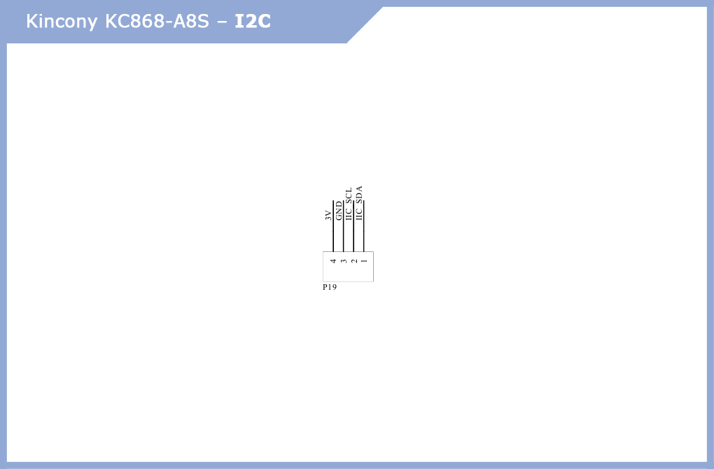
A separate I2C connector allows you to connect all additional components compatible with I2C (for example, the display) to the controller and significantly expand the functionality of the controller.
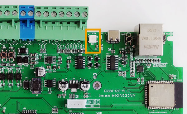
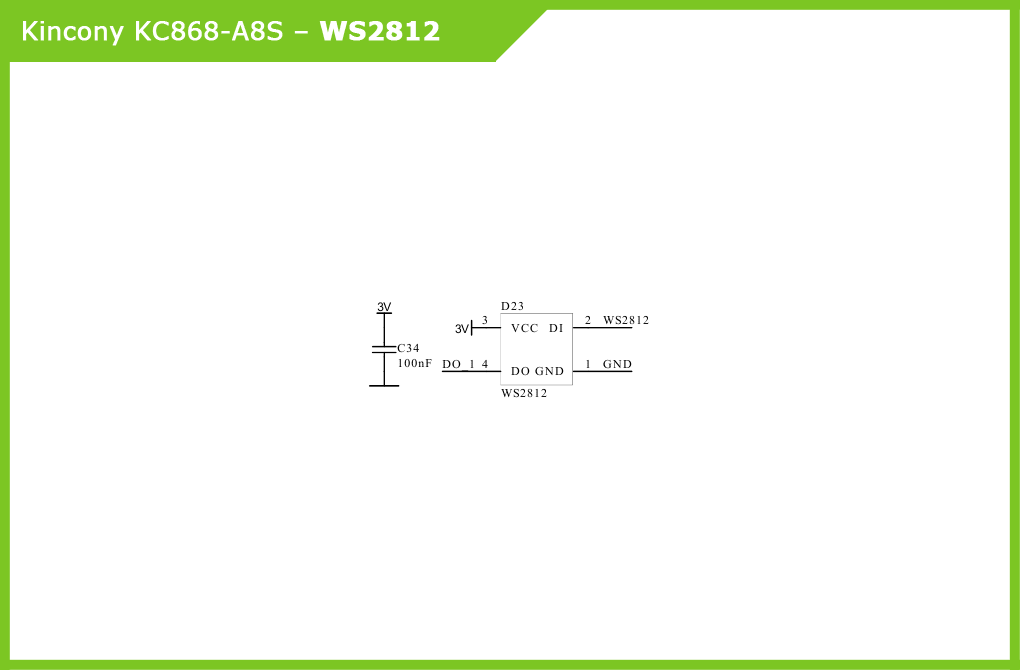
WS2812
The RGB LED WS2812 allows you to visualize the status of the controller and inform users about various events in the system. Schematic diagram of LED connection WS2812:
GSM
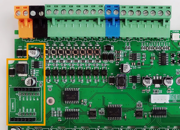
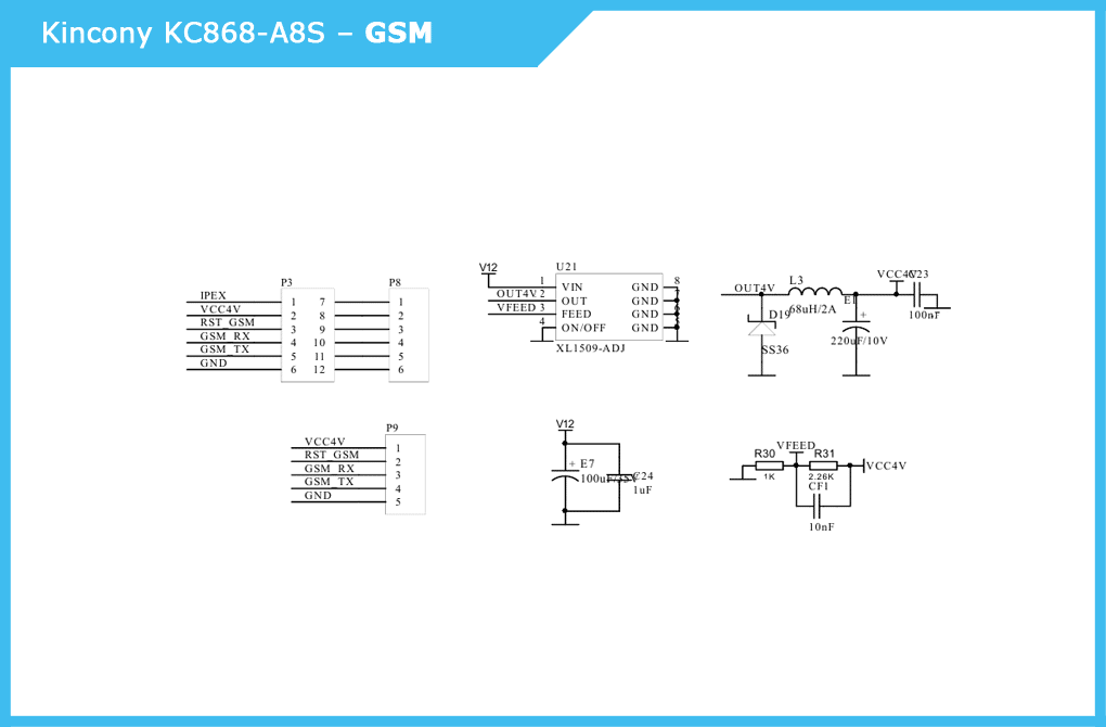
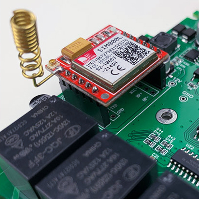
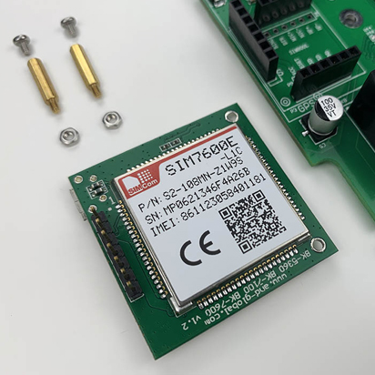
The main “chip” KC868-A8S. Connecting the GSM module allows you to control the controller over GSM networks and significantly expands the functionality of your IoT solutions. The basic version allows you to install the popular SIM800L module. Circuit diagram of the connection of the GSM module: Photo of the SIM800L module installed in the KC868-A8S controller. Instead of a spring antenna, you can use a full-fledged remote antenna (the photo shows the connector for it). New revisions of the KC868-A8S controller make it possible to install more advanced GSM modules, for example, SIM7600E, as in the images below.
Pin Layout (Pinout)
Pinout controller KC868-A8S, which gives a comprehensive idea of what and how it is related to esp-WROOM-32 on the board.
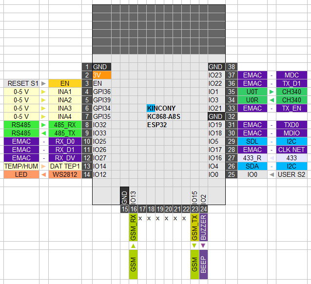
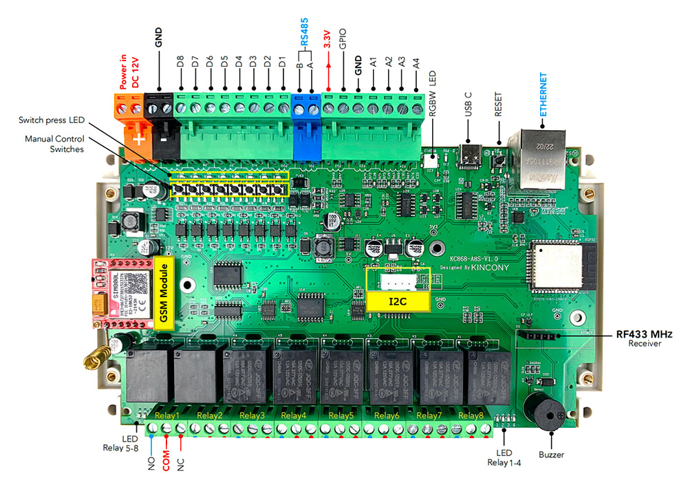
Diagram of external connections
Corrected and cultivated (as far as possible) diagram of the external connections of the KC868-A8S controller manufacturer.
Conclusion
In conclusion, I would say that the presence of the GSM module in the controller makes this controller a more interesting solution than conventional controllers – it becomes possible to work directly with the mobile operator, even if the router breaks down, and Wi-Fi and Ethernet connections do not work, your system can continue to work, transmit data and receive commands from anywhere on the planet, where there is a mobile connection.
