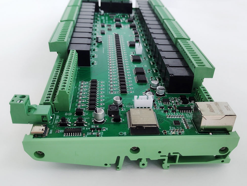
How many relays can be installed on the controller board? Four? Eight? Kincony decided not to limit itself and equipped its KC868-A32 model of ESP32 board with as many as 32 relays. The result was a unique controller, which I don’t remember any analogues – against the background of ordinary devices of this type, the KC868-A32 looks like a flagship aircraft carrier.
The dimensions of the KC868-A32 are such that this work of creative Chinese thought will not fit into every electrical distribution box, you can take it under your arm like a board and if you attach wheels to it, then ride it like a skateboard.
Extreme dimensions and an incredible number of relays on board are far from all the advantages of Kincony KC868-A32, then we will analyze in detail the device, circuitry and applications of this controller.
Kincony KC868-A32
Since our “aircraft carrier” belongs to the family of KC868 controllers operating under the control of ESP32, it also has on board the ESP-WROOM-32 module with all its inherent capabilities (Wi-Fi, Bluetooth, etc.). In addition to ESP-WROOM-32, Kincony KC868-A32 contains:
- 32 digital optoisolated inputs “dry contact”;
- 4 analog inputs 0-5 V;
- 32 relays 220 V, 10 A (COM, NO, NC);
- RS485 interface;
- I2C connector;
- Connector GSM/HMI;
- Ethernet LAN8270A;
- USB Type-C connector for programming and filling firmware;
- RESET and DOWNLOAD buttons;
- Powered by 12V DC;
- Dimensions: 320х122 mm.
32 digital inputs and 32 relays immediately define the KC868-A32’s target application area – projects where you need to receive data from multiple digital inputs and control different equipment using multiple relays. If your task fits into 32 inputs and 32 relays, then the KC868-A32 is a good choice for your project.
The KC868-A32 has a powerful MCU and supports a variety of interfaces – wireless Wi-Fi, Bluetooth, wired Ethernet and RS485, which allows you to create functional automation solutions on this controller.
I2C and GSM/HMI connectors further expand the capabilities of the controller and allow you to connect additional equipment and components to it.
The A32 board is intended for control installations with a large number of digital inputs, room switches, sensor switches, any ‘dry’ switches. By developing the appropriate software (IDE Arduino), a powerful control mechanism can be obtained as needed. It is special that the states of digital inputs can be combined with analog inputs (sensors of temperature, humidity, CO2, pressure …) and achieve control according to user requirements.
All relays are up to 10A, but this should be taken with some reserve, especially if they are inductive consumers (motors, compressors, …), so it is wise to use additional contactors for such consumers.
The KC868-A32 will delight such users, as it will be able to perform all needs with one controller.
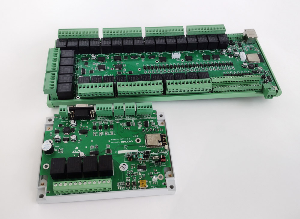
For comparison, A32 vs. to the “little brother” A4
Appearance of the controller
If the previous controllers of the KC868 series assumed the use of “closed” DIN-rail cases, then the KC868-A32 comes in a specialized “cut” profile, apparently due to the gigantic and non-standard dimensions of the controller. KC868-A32 will be located at the installation site in an open and unprotected form, including from dust.
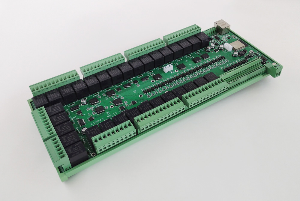
Board “as is”, without installation profile. Theoretically, it can be simply screwed to some surface through the appropriate holes. Also in the photo you can see the “two-story” connectors for connecting digital inputs.
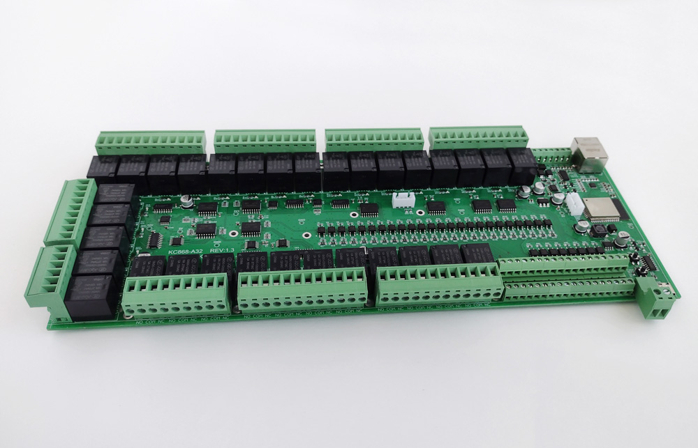
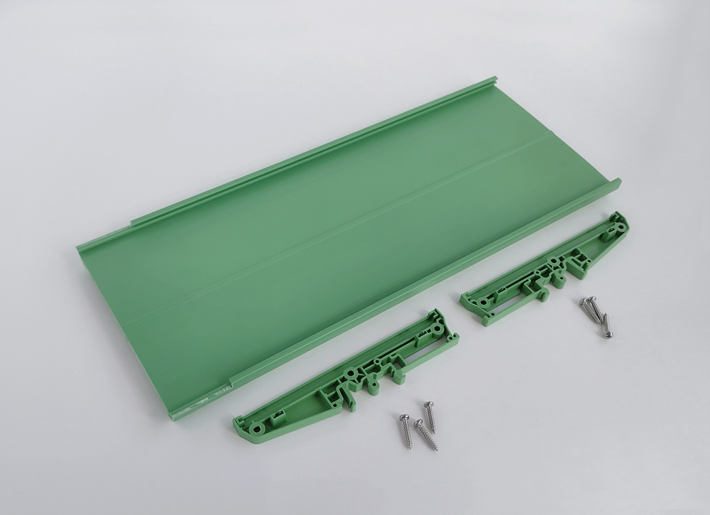
The profile is attached using three self-tapping screws on each side of the controller. In general, everything is done functionally and neatly – the left and right sides of the installation are even indicated on the side plugs.
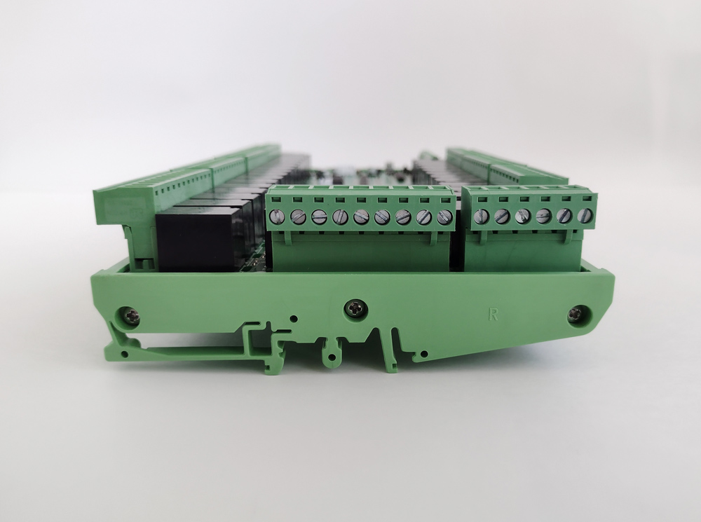
Profile photo show some minor modifications by hand to ensure normal access to the protruding connectors.
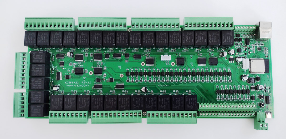
Motherboard KC868-A32
Top view of the KC868-A32 board and components installed on it. Check out the scope and train of thought of Chinese engineers.
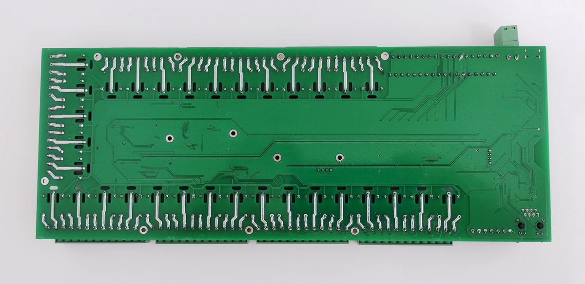
View of the board from the back. Protective cuts in the textolite are visible – we will leave to judge how effective and competently they are. And again, the “window” for the ESP32 antenna in the foil is made minimal. It is not entirely clear what prevents it from being made a little larger.
Circuitry
Let’s move on to the analysis of the KC868-A32 circuitry. For each functional block, I will give a photo of the components of this block on the controller board and its circuit diagram, and I will also supplement this description with comments.
▍ Power supply
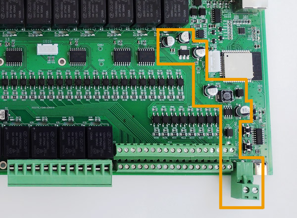
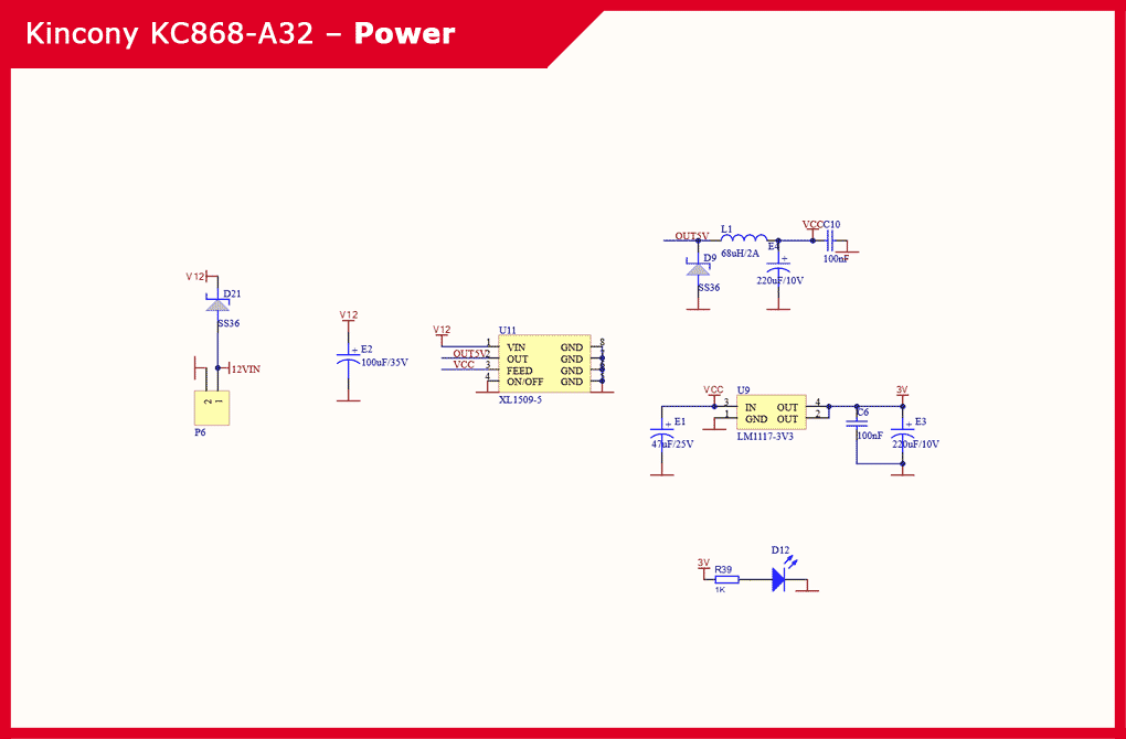
The power subsystem of the KC868-A32 controller consists of an XL1509-5 step-down DC-DC converter chip for generating voltages of 12 V and 5 V and a linear regulator LM117-3V3 for generating a voltage of 3.3 V. All this is equipped with an appropriate harness.
The photo shows that the components of the power subsystem are scattered around the board in the form of a bizarre labyrinth, this is due to the fact that the lion’s share of the space on the board is occupied by the relay subsystem, and the power components had to be placed “according to the residual principle.”
Schematic diagram of the power subsystem KC868-A32:
▍ ESP32
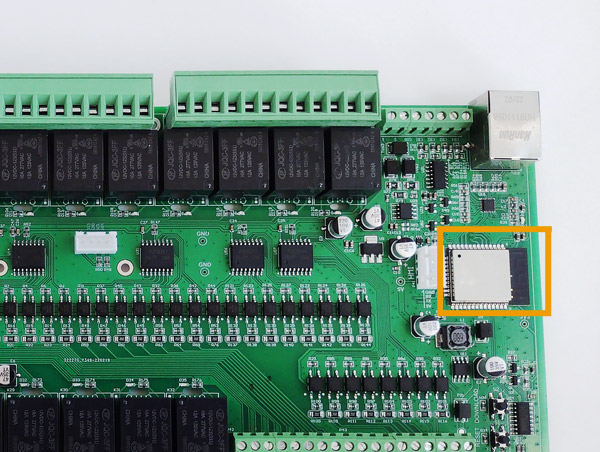
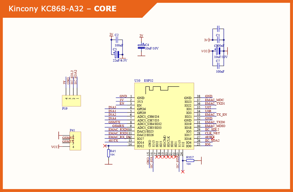
The Kincony KC868-A32 has an ESP32 module in the ESP-WROOM-32 modification. Also on the board there are capacitors designed to filter the supply voltage.
Schematic diagram and pinout of the core (ESP32) of the controller:
▍ USB/CH340
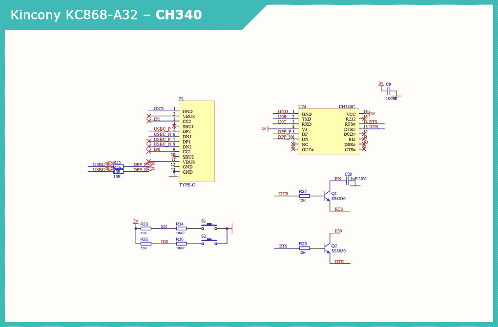
The KC868-A32 computer connection and programming subsystem uses a Type-C USB connector. The operation of this block is provided by the CH340C chip. There are also two buttons RESET and DOWNLOAD.

Schematic diagram of the subsystem USB / CH340 controller:
▍ Digital inputs
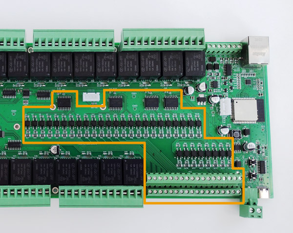
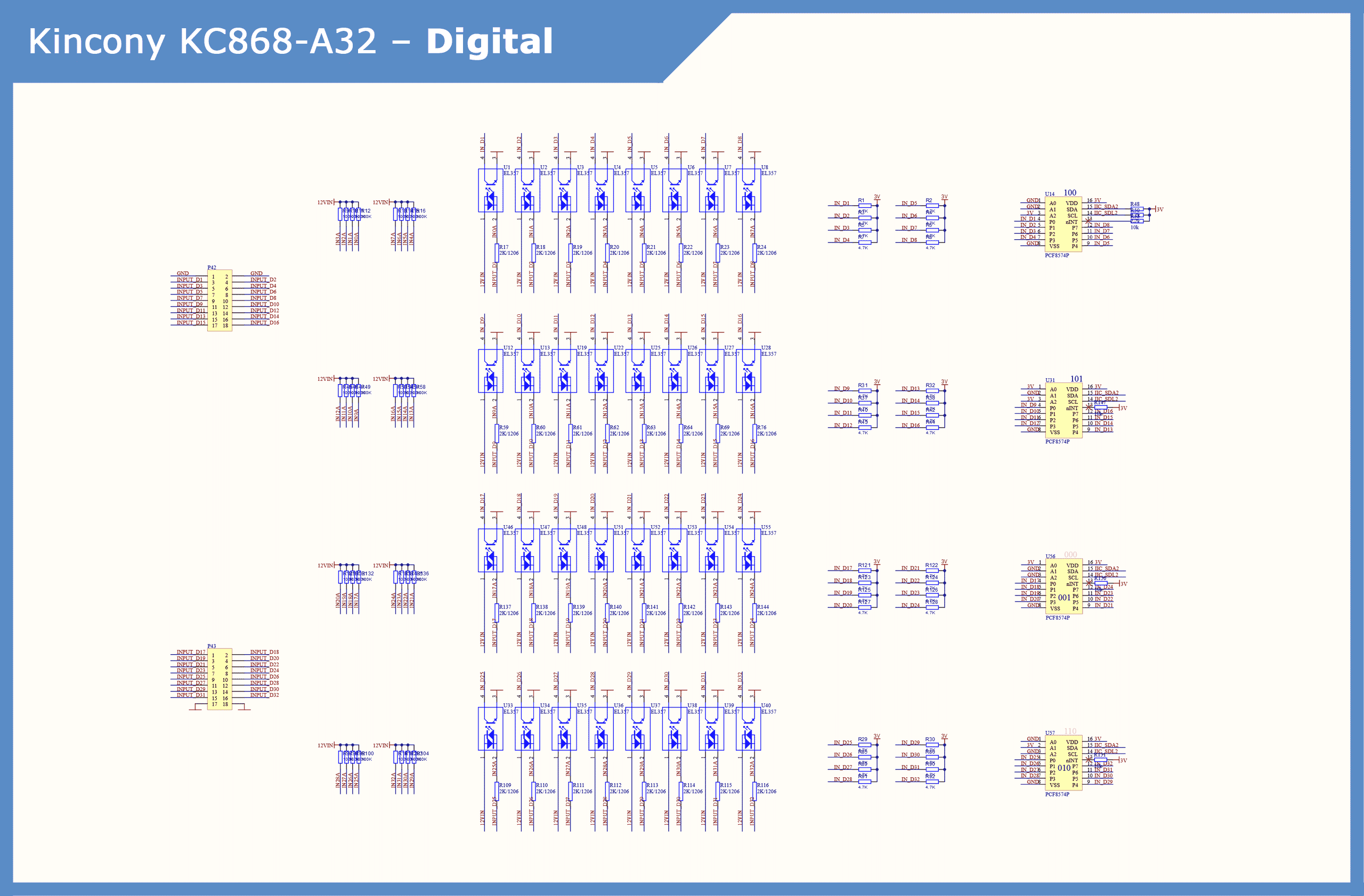
The Kincony KC868-A32 board has 32 digital opto-isolated dry contact inputs on EL357 optocouplers. To ensure the operation of 32 digital inputs in conjunction with the ESP32, with its limited number of free GPIOs, the KC868-A32 uses a digital input / output expander with an I2C interface on four PCF8574P chips.
Due to the large number of digital inputs, this subsystem occupies a significant area of the KC868-A32 controller board.
Schematic diagram of the digital input subsystem:
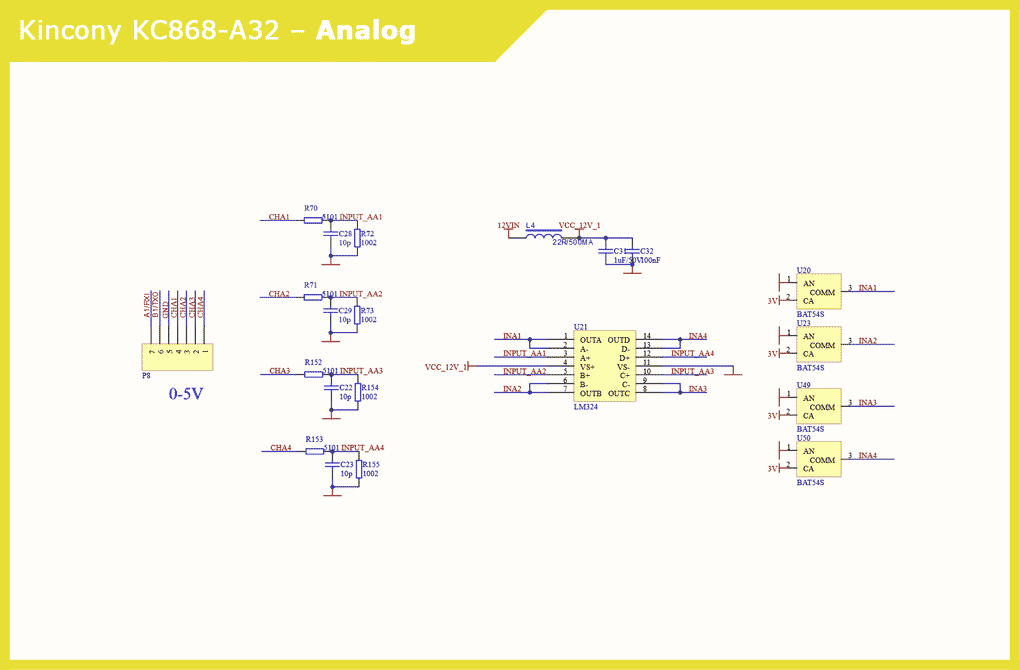
▍ Analog inputs
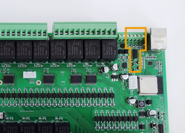
The KC868-A32 board has 4 analog inputs for 0-5 V signals. The voltage is generated by the input stages, the LM324 quad op-amp, and the BAT54S Schottky diodes.
The voltage VCC_12V_1 is immediately formed. You can notice that Kincony uses the same type of solutions in their controllers, sometimes copying them 1:1 in different models.
Schematic diagram of the analog input subsystem:
▍ Relay
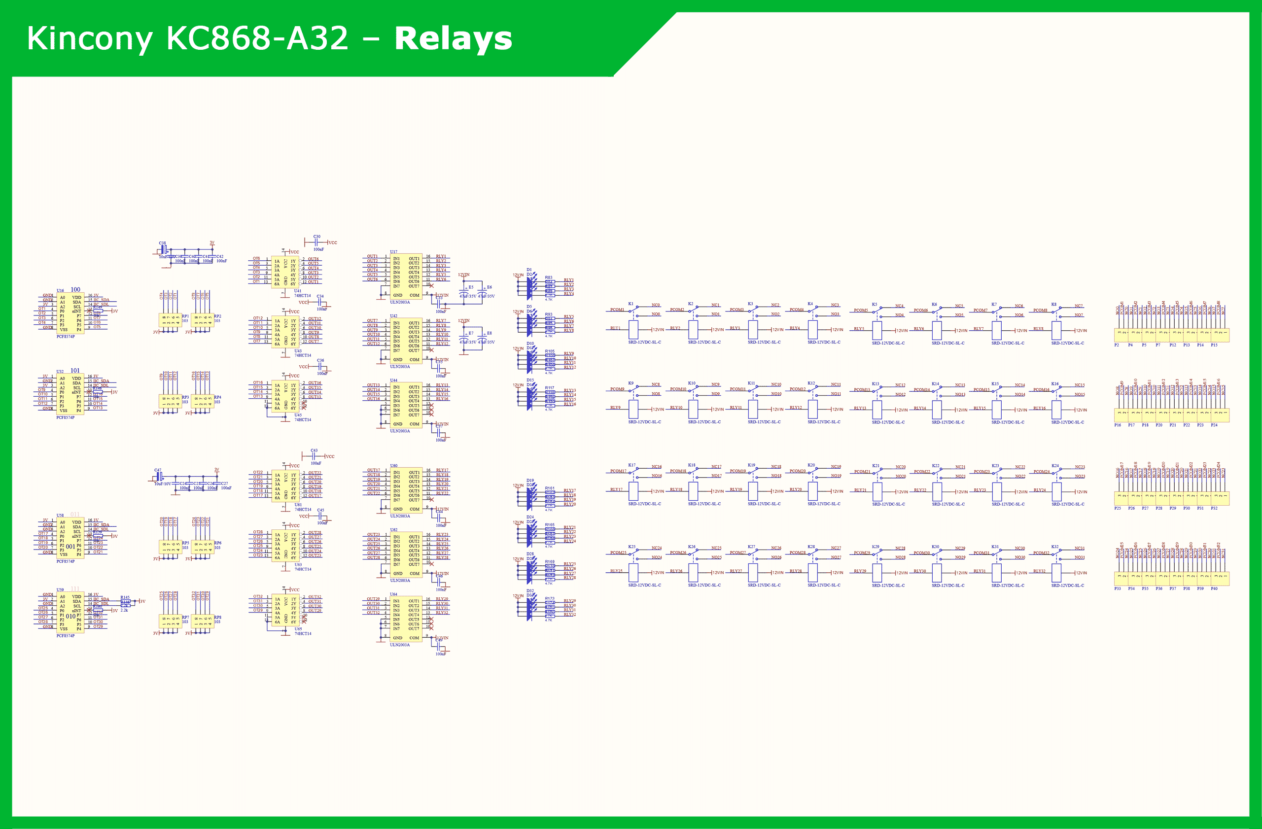
The lion’s share of the KC868-A32 controller board is occupied by the relay subsystem. The interaction of this subsystem with the ESP32 microcontroller is carried out using four digital input / output expanders with an I2C interface PCF8574P. 32 relays are serviced by 74HCT14 microcircuits with inverting Schmitt triggers and ULN2003A with Darlington transistor arrays.

▍ Ethernet
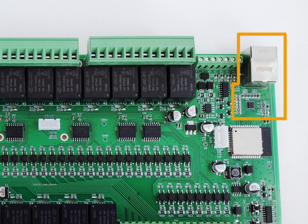
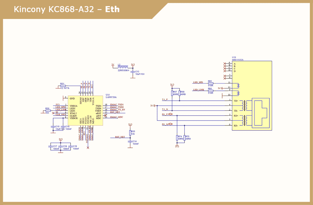
The Kincony KC868-A32 controller is equipped with a wired Ethernet interface based on the LAN8270A chip. This allows you to connect the controller via Wi-Fi or Ethernet or simultaneously via two interfaces. There are also various advanced options for using the capabilities built into the KC868-A32 controller, for example, using the second interface as a reserve, etc.
Schematic diagram of the Ethernet subsystem:
▍ RS485
For such a device as the KC868-A32, it would not be superfluous to have an RS485 interface on board, which was implemented by Kincony. This will make it quite easy to connect a lot of additional specialized equipment to the KC868-A32.
RS485 is a powerful interface for applications in professional industrial solutions. Although the RS485 is a very old interface, the ModBus protocol is still very much present in all industrial applications. It is especially attractive that ModBus RS485 devices can be up to 1000m away from the Master controller.
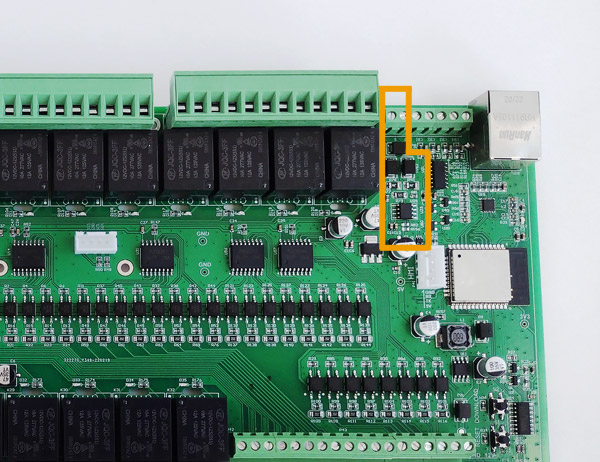
The RS485 subsystem is provided by the MAX13487EESA interface driver, the 74LVC1G125 buffer, and the appropriate binding elements.

▍ I2C
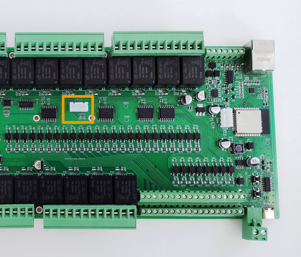
The presence of an I2C connector on the KC868-A32 board is very useful – thanks to it, you can connect various I2C components to the controller, such as a display or additional sensors.
▍ GSM/HMI
Mysterious GSM/HMI connector. What Kincony wanted to say with this is not entirely clear, but judging by the schematic diagram, the GPIO32 and GPIO33 contacts are directly connected to this connector. You can connect “Serial HMI Display” or any components you need to them, with the appropriate number of pins and operation logic. Mysterious GSM/HMI connector. What Kincony wanted to say with this is not entirely clear, but judging by the schematic diagram, the GPIO32 and GPIO33 contacts are directly connected to this connector. You can connect “Serial HMI Display” or any components you need to them, with the appropriate number of pins and operation logic.
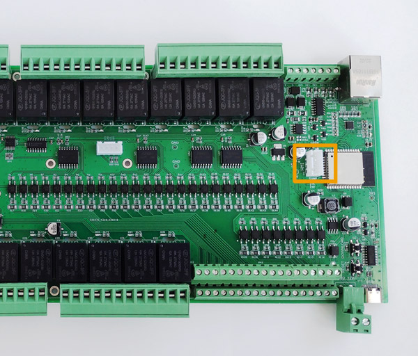
Diagram of external connections
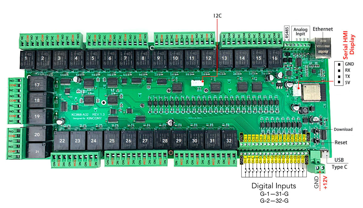
Next, I give a slightly cultivated official diagram of the connectors and external connections of the KC868-A32 controller.
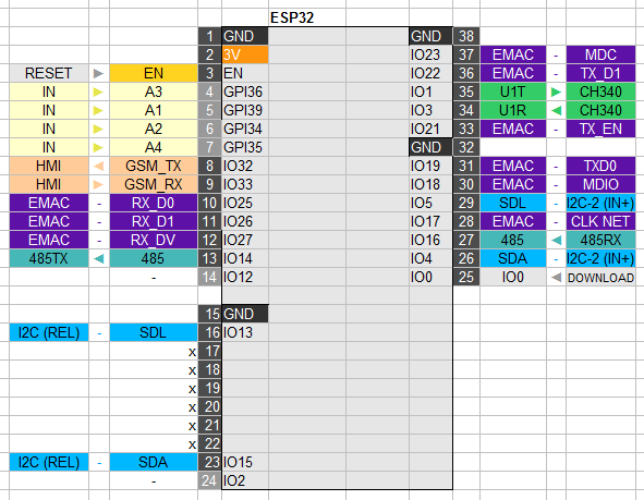
Pinout
Below is the pinout of the KC868-A32, which clearly shows all the connections to the ESP32 central module. Using this pinout, you can get a complete picture of what and how is connected on the KC868-A32 board.
Conclusion
As I noted above, if your project requires a large number of digital inputs and a large number of relays, then the Kincony KC868-A32 can be an excellent choice – it alone can replace many individual blocks and controllers. The main thing is that there is enough space in your electrical distribution box for this size.
If there is interest from the audience, I should prepare some program’s of the KC868-A32 with ready-made examples of sketches for working with relays, digital and analog inputs, Ethernet, etc.
You can order this controller at:


