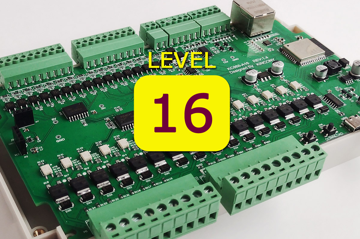
So, we have practiced on the initial Kincony controllers (KC868-A4, KC868-A8, KC868-Uair, KC868-AG) and now we are moving to the “big league” and will analyze the device and purpose of the more serious KC868-A16 controller. This is a representative of the same line of Kincony ESP32 controllers for DIY and small automation, but with a different architecture and some additional (long-awaited) features, for example, an integrated RS485 interface.
There is still the possibility of working both via wireless Wi-Fi and wired Ethernet, the ability to work with 433 MHz wireless devices and connect additional equipment, etc., but we will not get ahead of ourselves and try to figure out in detail what is Kincony KC868-A16 and how it can be used in your household.
Kincony KC868-A16
To begin with, we will conduct a formal inventory of the equipment and functional blocks available on board the KC868-A16. First of all, of course, this is the “brain” of the entire system – the ESP32 microcontroller (ESP-WROOM-32) with all its capabilities (Wi-Fi, Bluetooth, 4 MB EEPROM, etc.).
In addition to ESP-WROOM-32, Kincony KC868-A16 contains:
- • 16 digital optoisolated inputs (“dry contact”);
- • 4 analog inputs 0–5 V;
- • 16 MOSFET outputs 12/24 V to control relays and other equipment;
- • Possibility to connect block KC868-E16 for 16 relays or similar;
- • 3 contacts for connection of temperature and other sensors;
- • Modules of the receiver/transmitter 433 MHz;
- • RS485 interface;
- • I2C connector;
- • Ethernet LAN8270A;
- • USB Type-C connector for programming and uploading firmware;
- • Powered by 12 V DC.
As we can see, the list of functional blocks and capabilities of the KC868-A16 is quite impressive – 16 digital inputs and 16 MOSFET outputs allow you to create quite advanced automation projects on this controller. In addition, the presence of analog inputs and GPIO for working with various sensors, as well as a free I2C connector, makes it possible to connect additional equipment you need.
The list of interfaces is also quite impressive: there are wireless Wi-Fi, Bluetooth, 433 MHz, and wired Ethernet and RS485 – all this allows you to cover most of the needs of small automation and, in general, the KC868-A16 looks like a pretty “strong” solution. This is already a higher-level controller than the Kincony controllers we reviewed earlier.
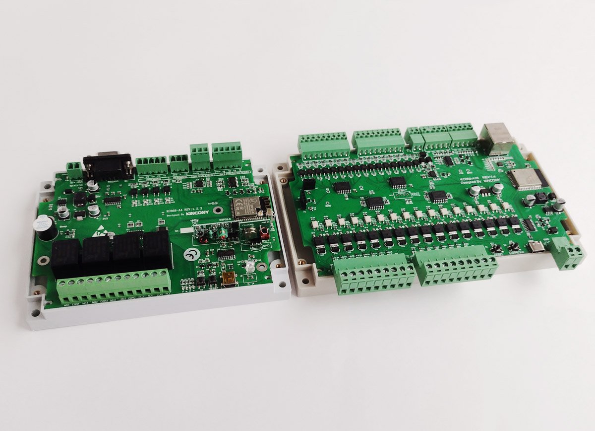
For comparison A4 and A16 side by side
For the “seriousness” of the KC868-A16, I had to pay with the loss of the relay – firstly, it is rather problematic to install 16 relays on the board, and secondly, MOSFET outputs can be used not only for relays, but also for controlling other equipment, for example, contactors, solenoid valves and other similar devices. Therefore, replacing the relay with blocks with 16 MOSFET outputs seems reasonable and quite appropriate in the context of the purpose and scope of the KC868-A16.
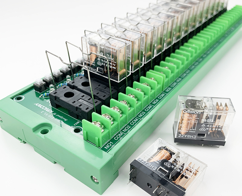
Relay box KC868-E16 designed to work in conjunction with KC868-A16
Appearance
The KC868-A16 comes with a housing of the same design as the KC868-A4 and KC868-A8 controllers, but only slightly longer. Also striking is a different color of plastic and the absence of technological holes and plugs on the top cover of the case. In general, I would rate the quality of the case for KC868-A4 and KC868-A8 at “5”, and the quality of the case for KC868-A16 at “4+”.
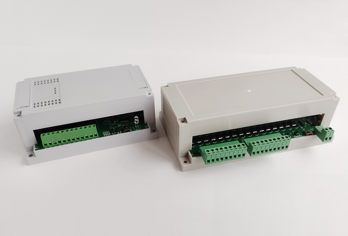
View of the KC868-A16 with the top housing cover removed. It can be noted that the board does not have strongly protruding parts and there is a lot of space left in the case for placing an additional board or display.
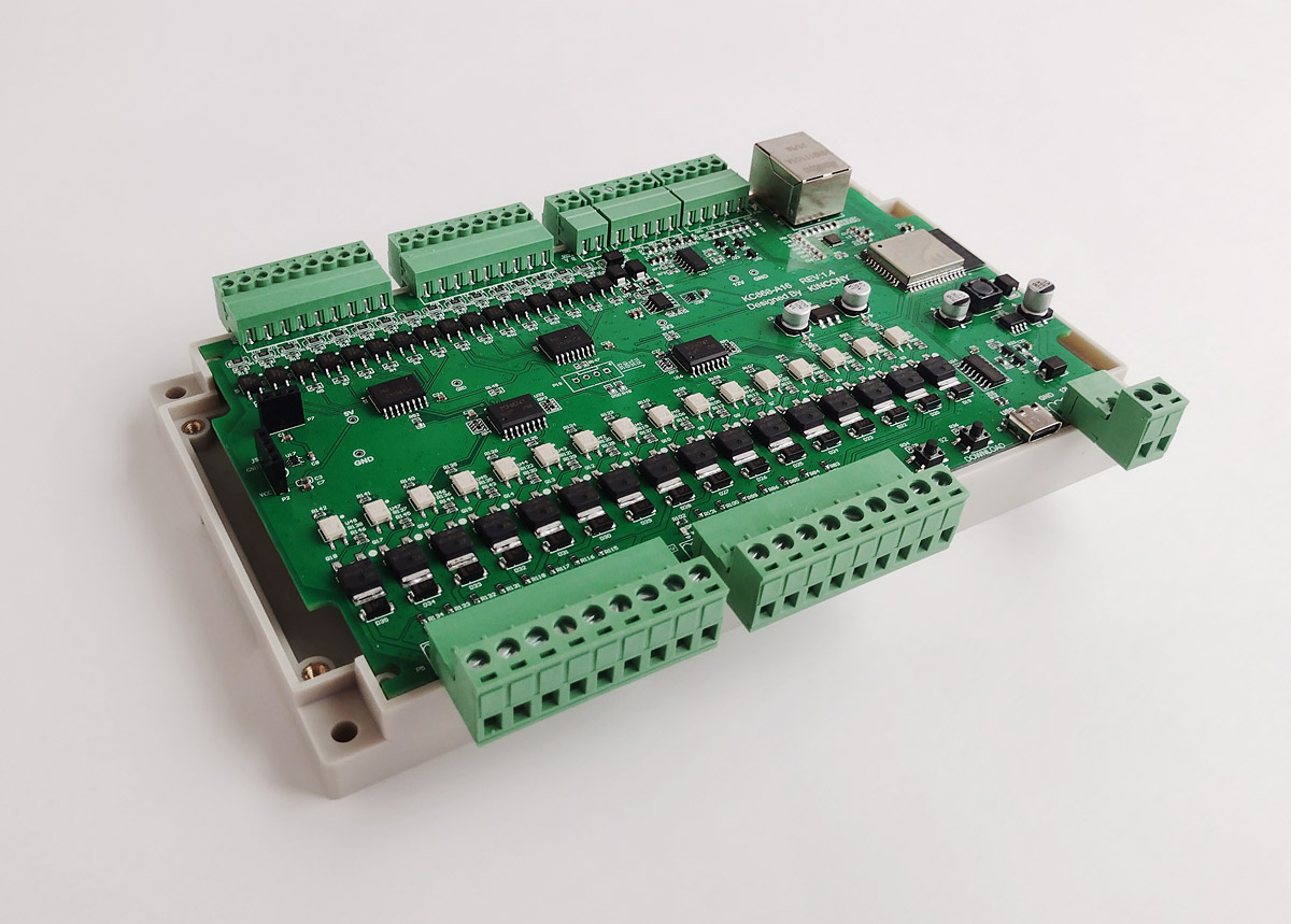
Board without case, view from the side of the Ethernet connector. You can see the connectors for digital inputs, RS485 interface, analog inputs and a connector for connecting additional sensors.
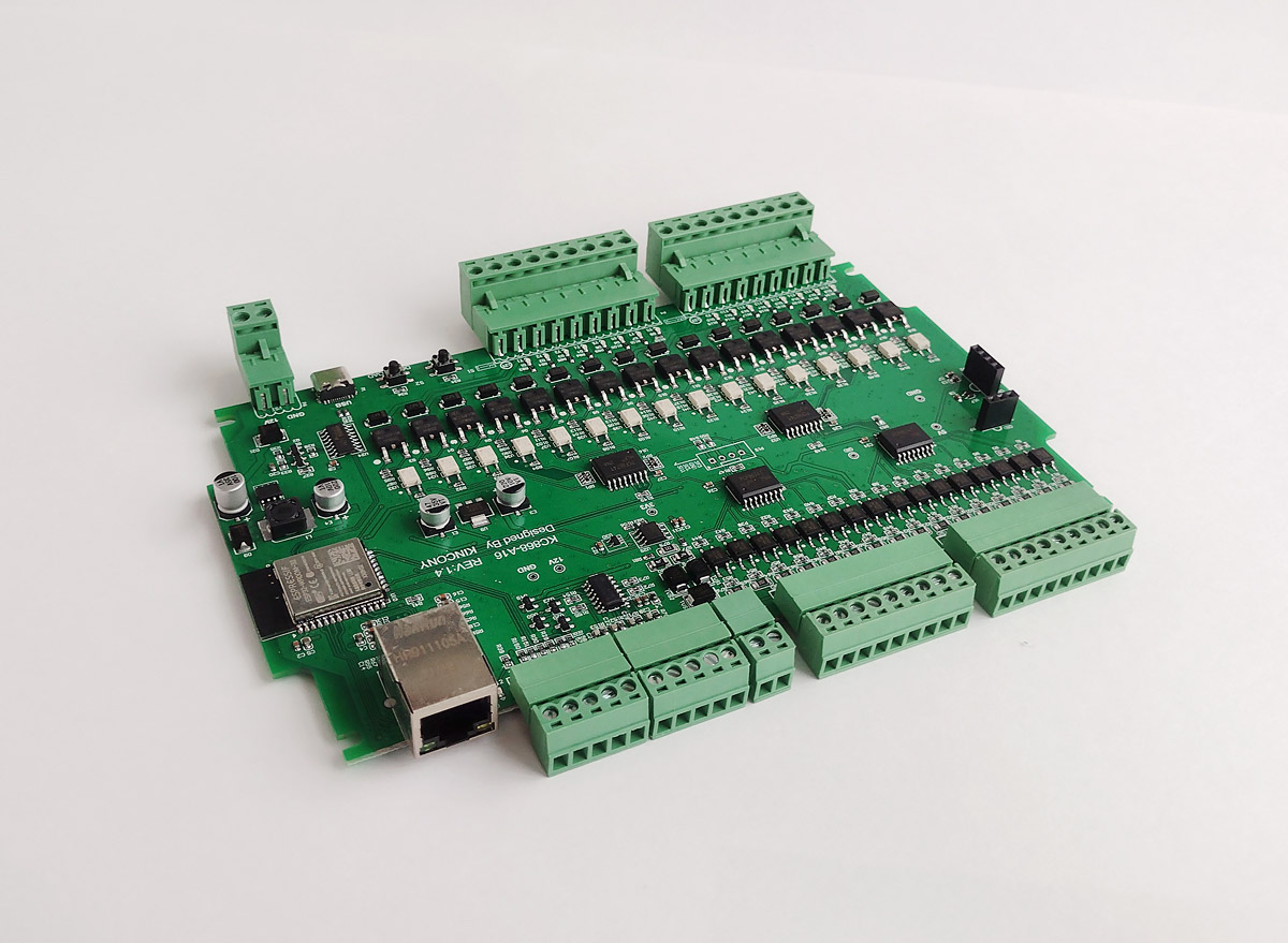
A look inside KC868-A16
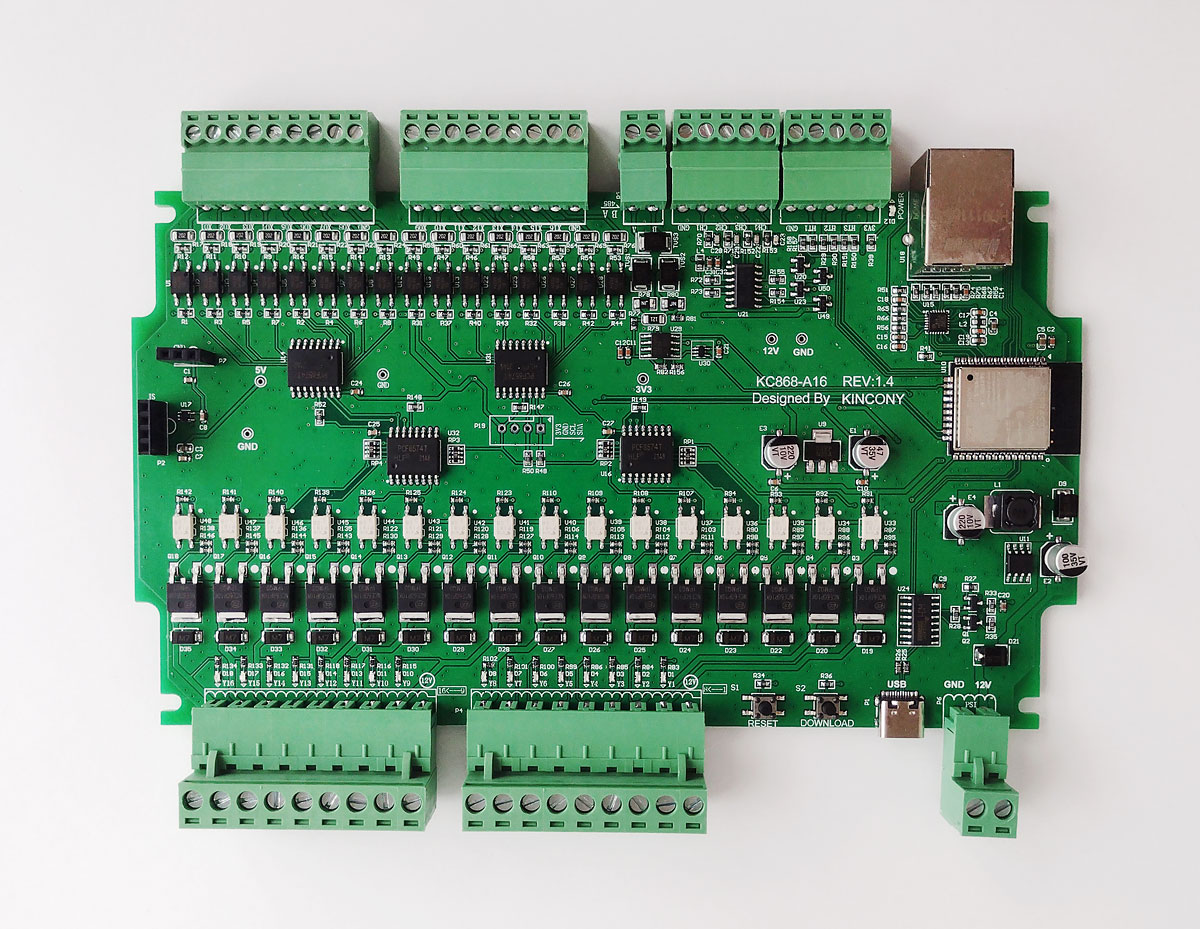
Top view of the KC868-A16 board and components installed on it. Everything is done with high quality and neatly – I have no complaints about the appearance of the board.
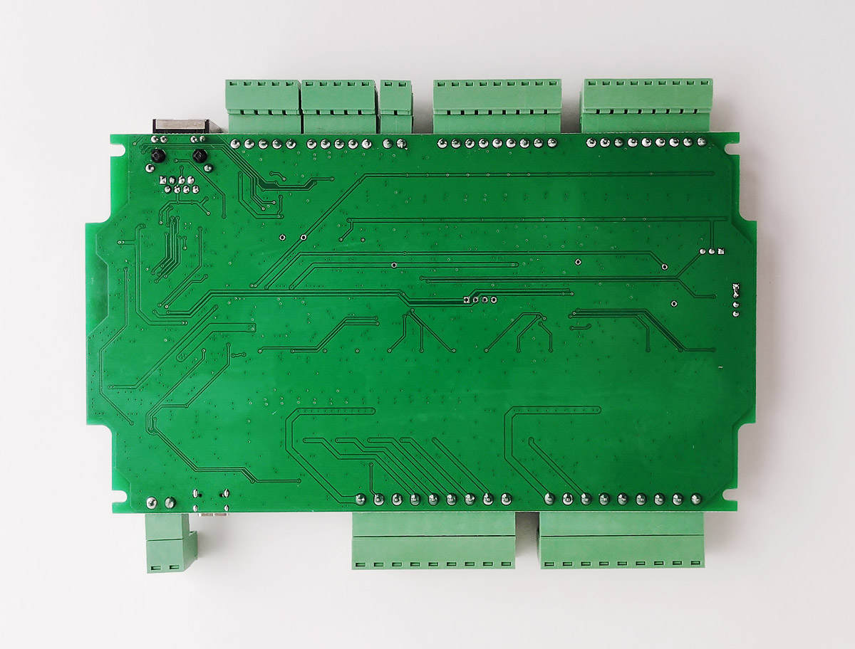
View from the back. Details on the underside are completely missing. The only remark is that I would make the “window” for the ESP32 antenna should be a little larger.
Circuitry
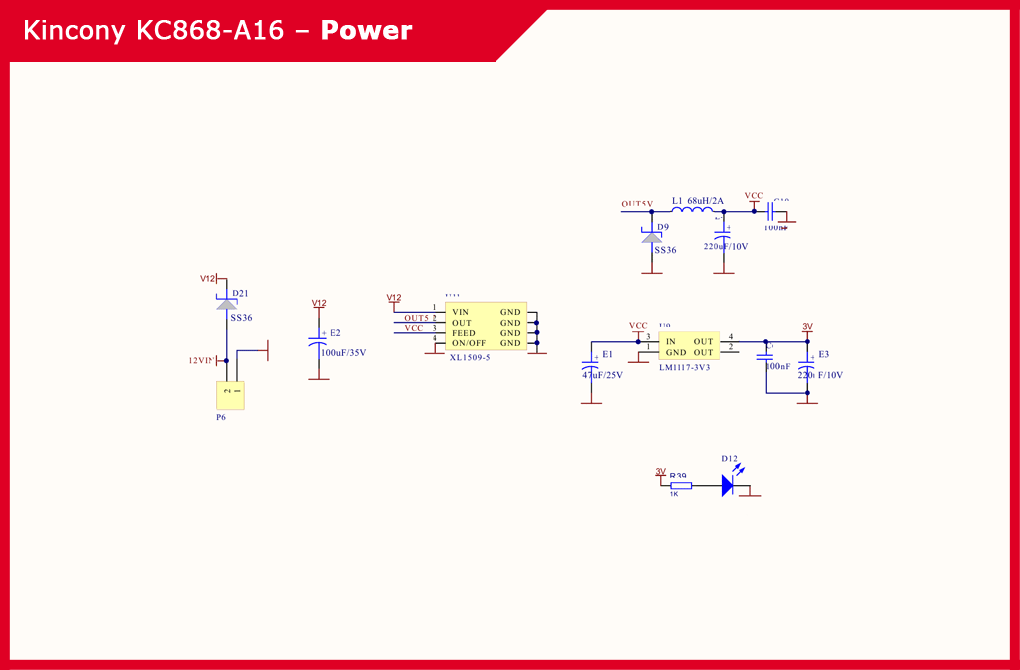
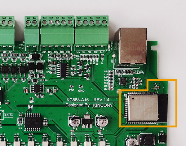
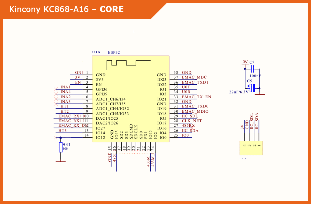
Now let’s analyze the circuitry of the KC868-A16. For each functional block, I will give a photo of the components of this block on the controller board and its circuit diagram, and I will also supplement this description with my comments.
▍ Power supply
The power subsystem of the KC868-A16 controller consists of an XL1509-5 step-down DC-DC converter chip for generating 12 V and 5 V voltages and an LM117-3V3 linear regulator for generating a voltage of 3.3 V.
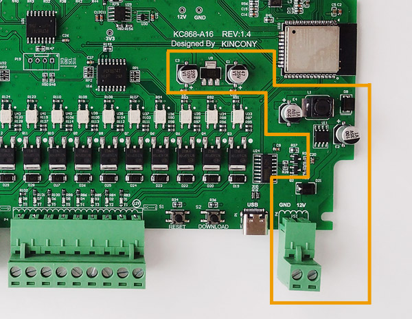
Schematic diagram of the power subsystem KC868-A16:
▍ ESP32
The Kincony KC868-A16 has an ESP32 module in the ESP-WROOM-32 modification. Previously, ESP32-S modules were installed in some models of the KC868 line, but now the company has completely switched to completing these controllers with ESP-WROOM-32 modules.
Schematic diagram and pinout of the ESP32:
▍ USB/CH340
The subsystem for connecting to a computer and programming KC868-A16 pleases us with the appearance of a Type-C USB connector instead of the outdated Mini-USB. The very operation of this block is provided by the CH340C chip. There are also two buttons – “RESET” and “DOWNLOAD”. The location of the buttons allows you to access them without dismantling the top cover of the controller.
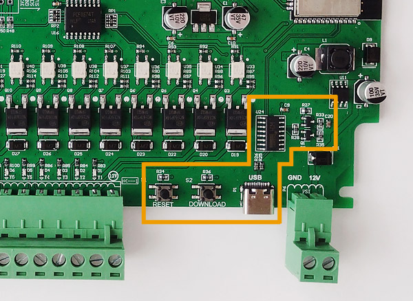
Schematic diagram of the subsystem USB / CH340 controller:

▍ Digital inputs
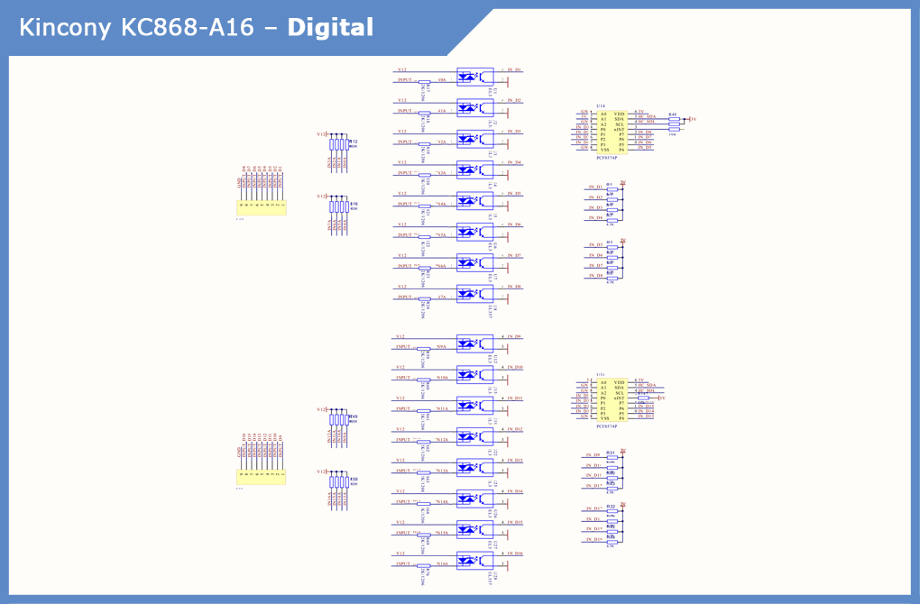
The Kincony KC868-A16 board has 16 digital opto-isolated dry contact inputs on EL357 optocouplers. There is no indication of the status of digital inputs (it ended on KC868-A4, which is a pity).
To ensure the operation of 16 digital inputs in conjunction with the ESP32 (with its limited number of free GPIOs), the KC868-A16 uses a digital input / output expander with an I2C interface on two PCF8574P chips.
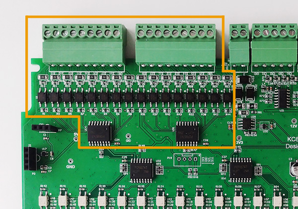
Schematic diagram of the digital input subsystem:
Analog inputs
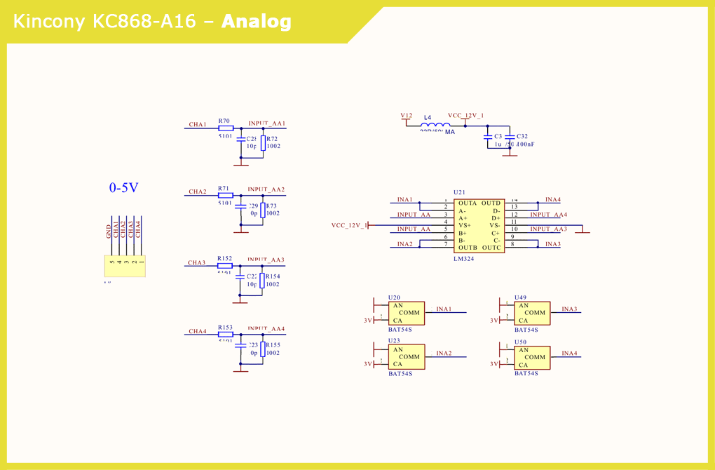
The KC868-A16 board has 4 analog inputs for 0-5 V signals. The voltage is generated by the input stages, the LM324 quad op-amp, and the BAT54S Schottky diodes. The voltage VCC_12V_1 is immediately formed.
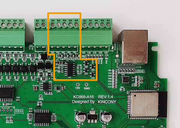
Schematic diagram of the analog input subsystem:
▍ MOSFET outputs
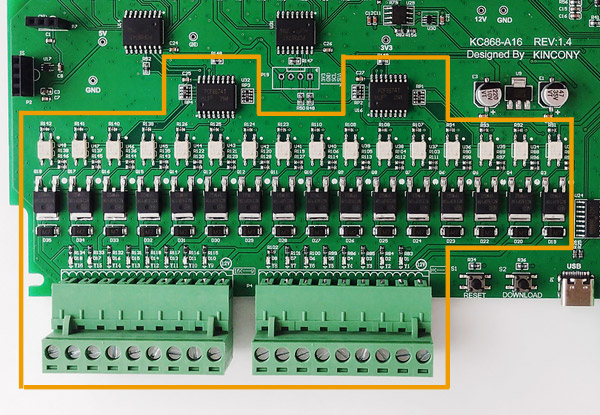
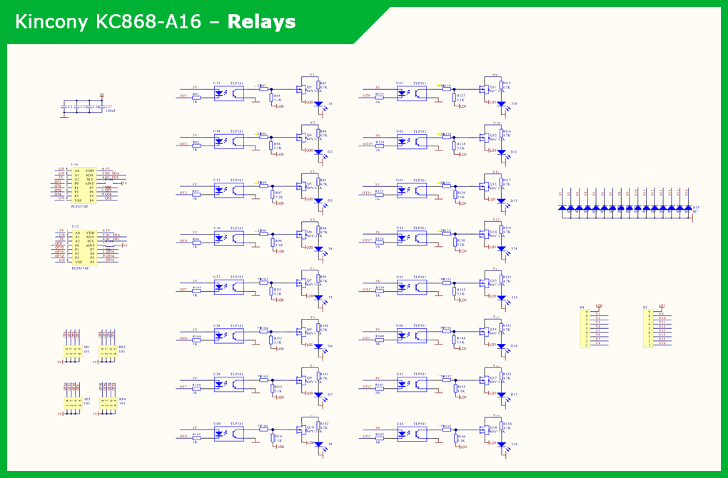
The largest subsystem of the KC868-A16 controller, which interacts with the ESP32 microcontroller using two digital input / output expanders with an I2C interface PCF8574P. Further, the control signals are sent to the TLP181 optocouplers, which, in turn, control the 16 NCE60P10K mosfets.
There are also indicator LEDs, by the glow of which you can determine the status of the outputs of the KC868-A16 controller.
Schematic diagram of the MOSFET output subsystem:
Next, I give a typical diagram for connecting a relay unit (in this case, KC868-E16) to a KC868-A16 controller. In general, everything is clear and you should not have any difficulties connecting the relay to the KC868-A16.

▍ Sensors (temperature/humidity, etc.)
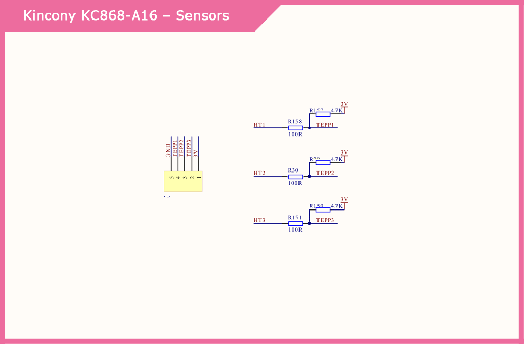
KC868-A16 has a connector with 3 free GPIO pins, to which you can connect any sensors or other components you need. You just need to pay attention that all these contacts are pulled up on the board to a voltage of 3 V.
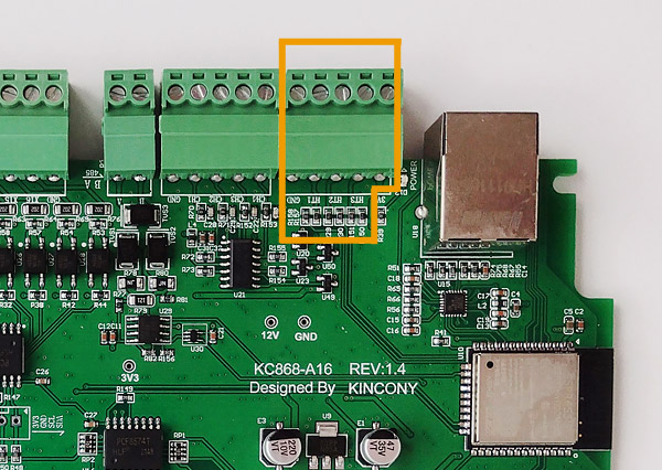
Schematic diagram of the sensor connection subsystem:
▍ 433 MHz modules
Here we see the implementation of a simple and obvious idea – not the wiring of the 433 MHz wireless modules themselves to the KC868-A16 board, but the wiring of the connectors instead. This makes it possible, if necessary, to quickly connect wireless modules or disconnect them by simply removing them from the connectors. This also allows you to get 2 additional free GPIOs in case you do not need a 433 MHz connection.
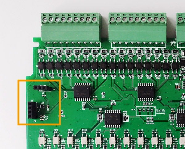
Schematic diagram of the subsystem for connecting wireless modules at 433 MHz:
▍ Ethernet
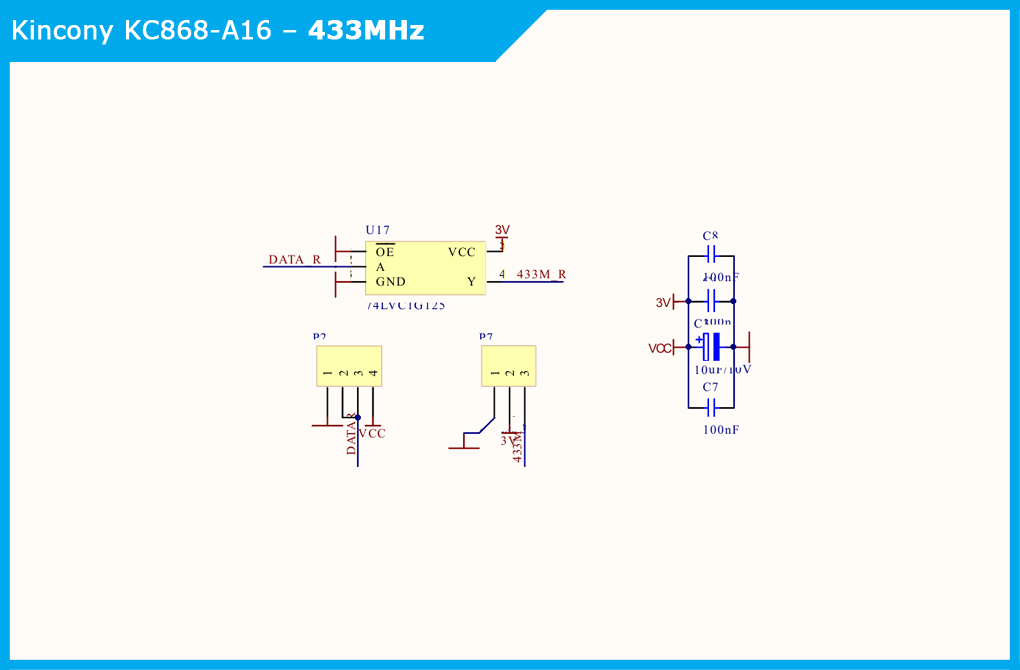
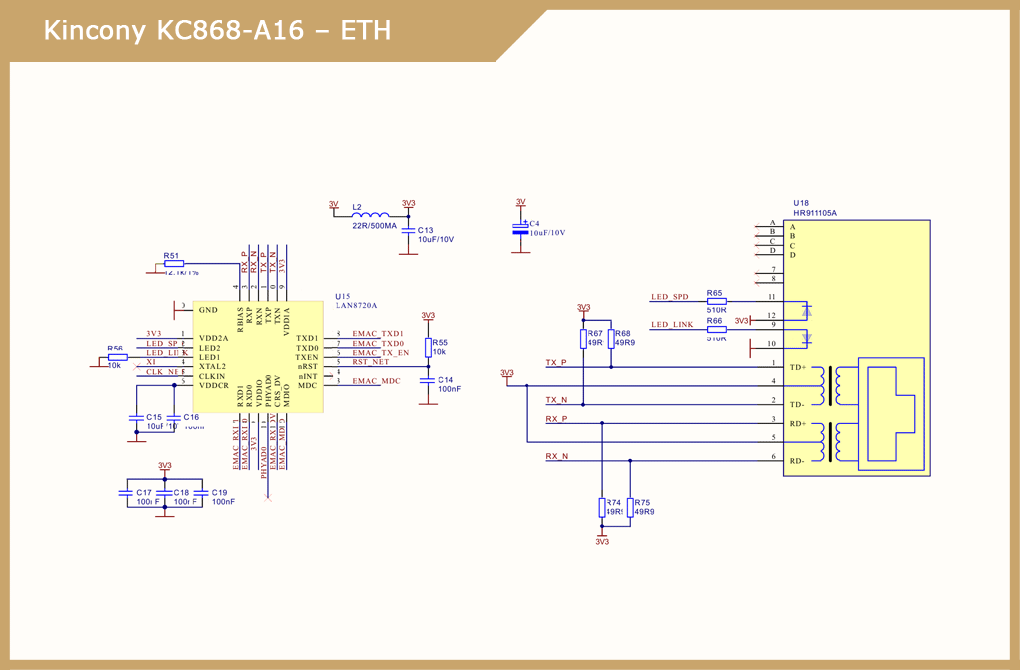
Контроллер Kincony KC868-A16 снабжён проводным Ethernet интерфейсом на чипе LAN8270A. Это позволяет подключать контроллер по Wi-Fi, или Ethernet, или одновременно по двум интерфейсам, или использовать второй интерфейс как резервный.
Расплатиться за возможность использования Ethernet интерфейса придётся потерей 9-и свободных GPIO из и без того крайне скудного их количества на ESP32.
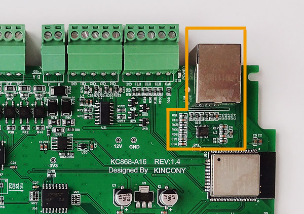
Schematic diagram of the Ethernet subsystem:
▍ RS485
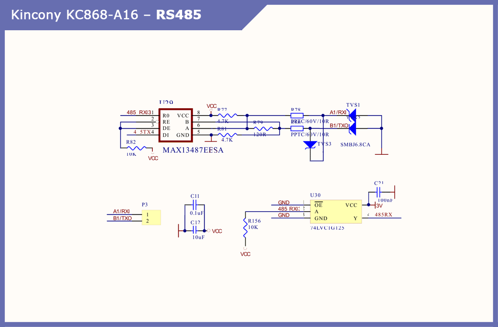
When considering the KC868-A4 and KC868-A8 controllers, everyone was missing an RS485 interface on board, and now Kincony heard the wishes of its users and added this interface to the board.
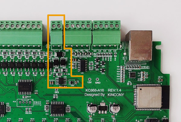
The RS485 subsystem is provided by the MAX13487EESA interface driver, the 74LVC1G125 buffer, and the appropriate binding elements.
▍ I2C
The presence of the I2C connector on the KC868-A16 board is hard to overestimate – thanks to it, we can connect various I2C components to the controller, for example, a display or additional sensors.
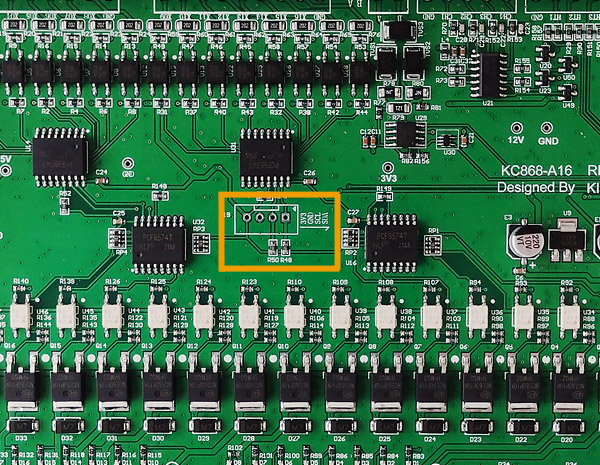
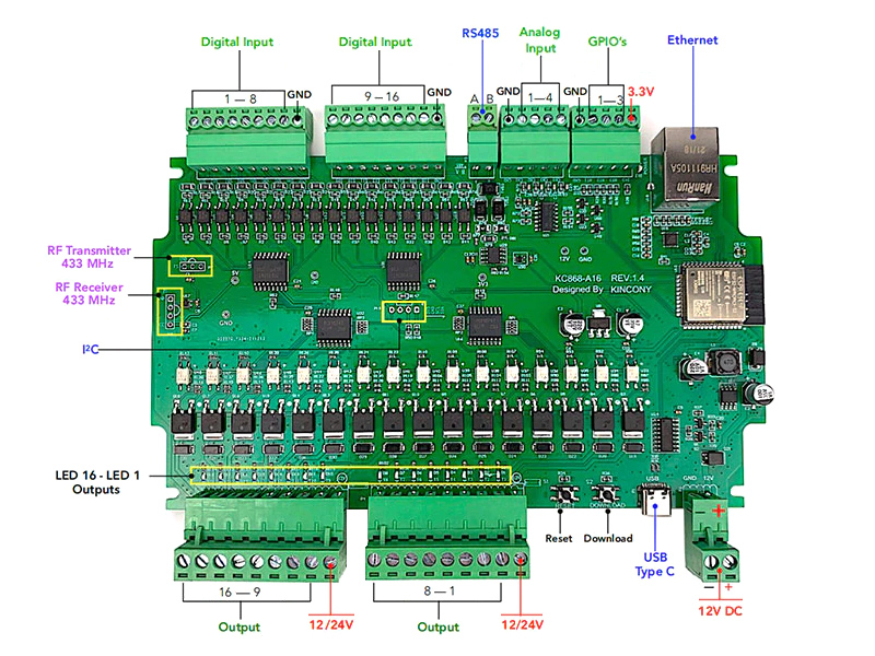
Diagram of external connections
Next, I give a slightly cultivated “original” diagram of connectors and external connections to the KC868-A16 controller.
Projects on KC868-A16
Well, in conclusion, I will give an example of a diagram of a simple project on the KC868-A16. This diagram clearly shows all the connection patterns of various equipment – how the controller itself is powered, how the relay unit is connected to it, how actuators are controlled, etc.
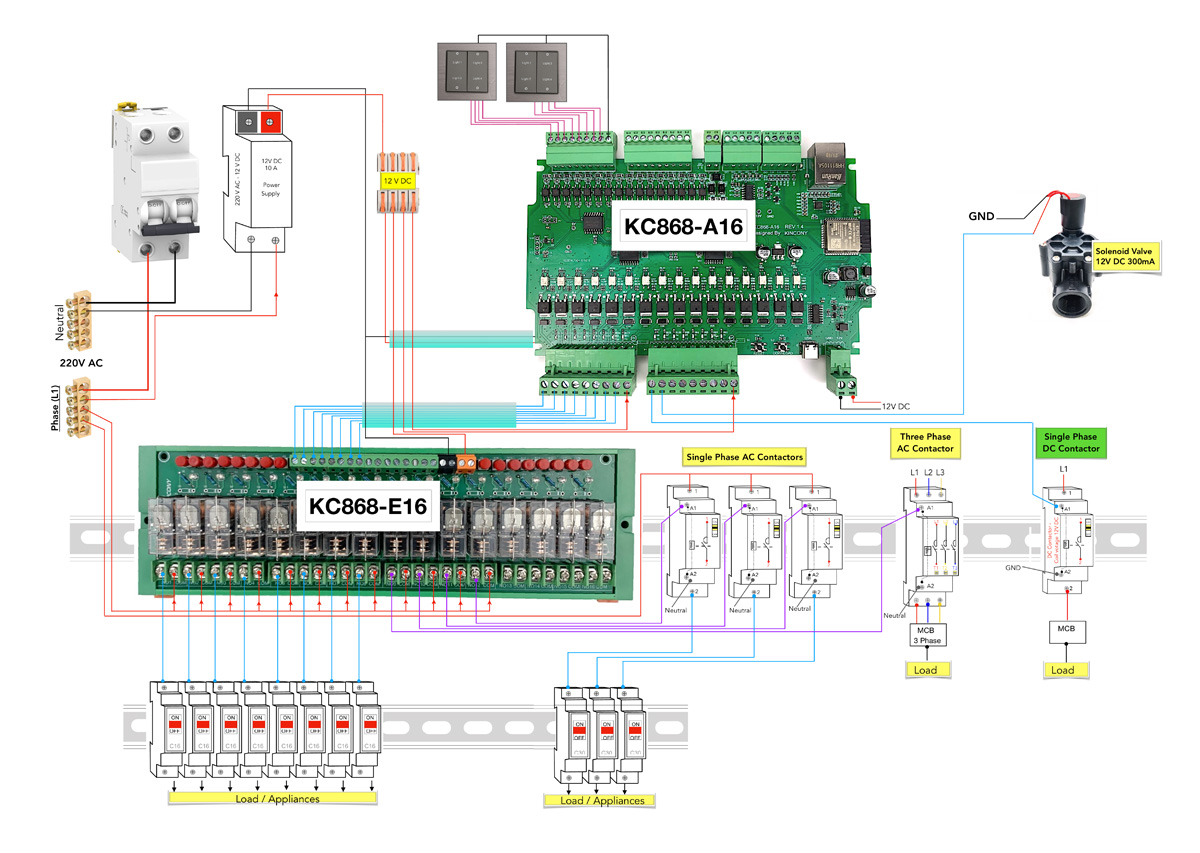
After reviewing this test circuit, you should have no questions about connecting equipment to the KC868-A16.
Conclusion
Well, our next journey into the interesting world of Kincony KC868 series microcontrollers has ended. I don’t know about you, but I was interested in understanding how the KC868-A16 works and I must say that the A16 met my expectations – this is an excellent controller for DIY home automation.


