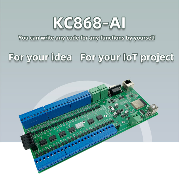
While we were dealing with the previous Kincony controllers, trying to apply them in smart projects, Kincony also no wasted time and released several more controllers that will find application in numerous data collection and processing projects to our satisfaction. This time it is the Kincony KC868-AI controller primarily intended to organize data collection from many inputs (48 digital inputs), plus communication modules that have been added to the controller panel. Receiver infrared signals (IR) and radio module at a frequency of 433 MHz. It turned out to be like universal (Wi-Fi, Ethernet) smart (ESP32) methods for collecting information from an object and transmitting it for further processing to another system. Well, the presence of RS485 and I2C interfaces and connectors with 4 free GPIO allows you to connect accessories to the KC868-AI, for example, a relay units and make this controller a full-fledged control element of your automation system. In the next steps, we will try to understand KC868-AI in more detail, and even deal with the programming.
❯ Kincony KC868-AI
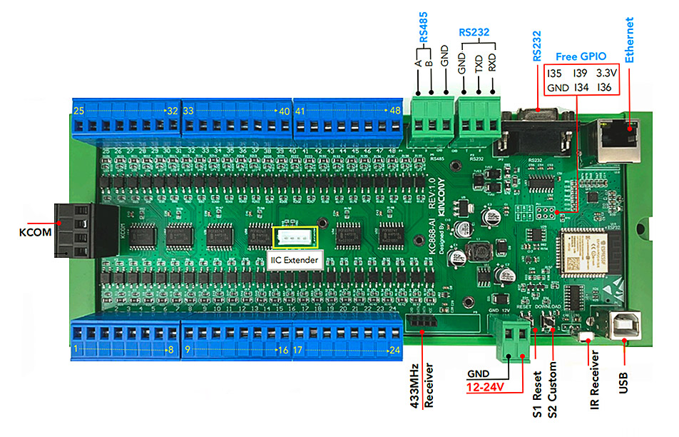
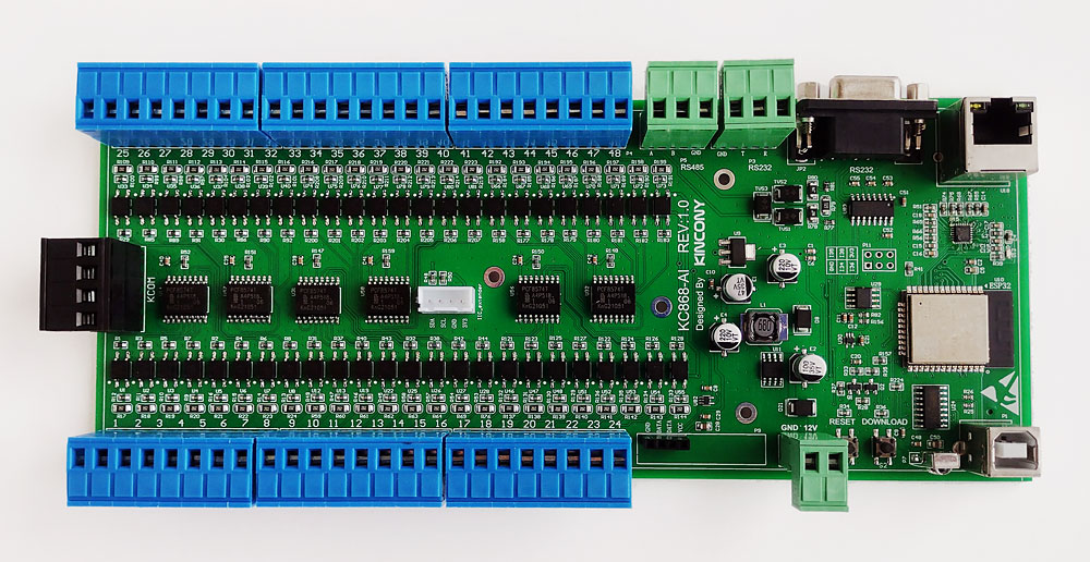
As always, we will begin with the listing of components and subsystems installed on the Kincony KC868-AI board:
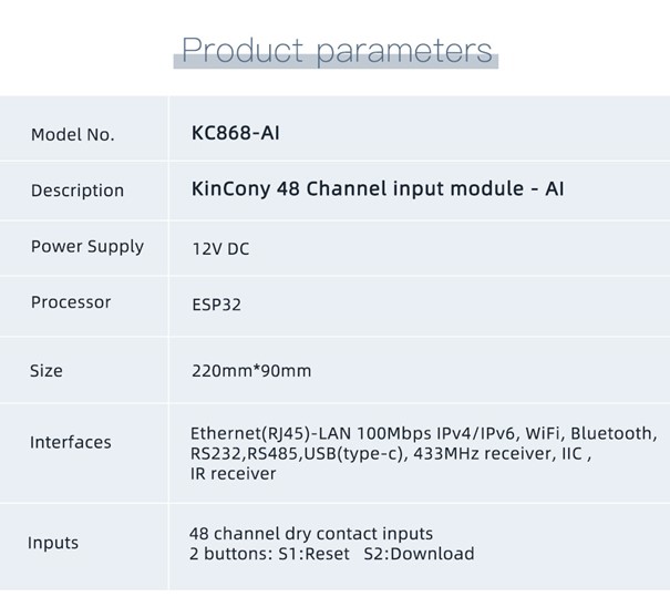
- Microcontroller ESP-WROOM-32E
- 48 digital optoisolated inputs (“dry contact”)
- 4-pin KCOM connector for digital inputs
- RS232 interface (2 connectors)
- RS485 interface
- 433 MHz receiver module connector
- IR receiver
- I2C Connector
- Connector with 4 free GPIOs
- Ethernet LAN8270A
- USB program connector
- Buttons restore and download
- Power Supply 12(24) V DC
So the inputs are:
- 48 digital inputs (“dry contact”)
- IR receiver
- 433 MHz receiver module connector
Interfaces:
- RS232 interface (2 connectors)
- RS485 interface
- I2C Connector
- Connector with 4 free GPIOs
Intercontroller communications:
- Wi-Fi (ESP32)
- Ethernet LAN8270A
From all of the above, an excellent flexible platform for creating its own automation solutions – the KC868-AI can be used as a device for collecting input data, which can then be transferred to a common system or as a separate universal controller for controlling an object (by connecting actuators, switches,… ). With this controller, you can also note the complete absence of analog inputs. On the board there is a connector witha free GPIO 34, 35, 36, 39 and you can try to connect some analog sensors to them, but for this you will have to make extra efforts. It is especially strange that in the name of the KC868-AI controller, it hints at AI – Analog Inputs, but the controller itself does not contain any analog input. Maybe Kincony alluded to “Artificial Intelligence” as “AI”?
❯ Appearance and design
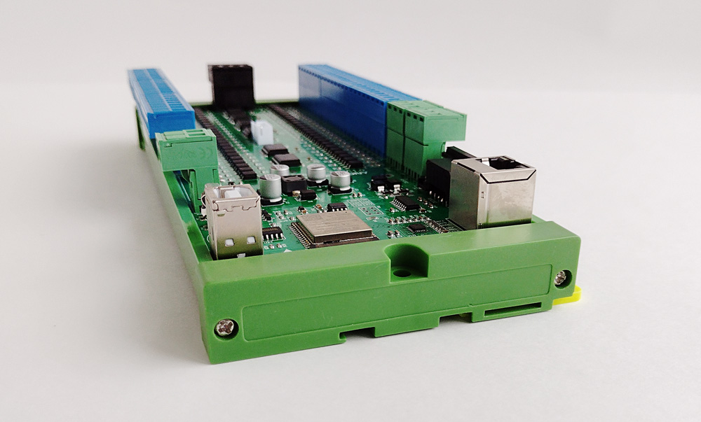
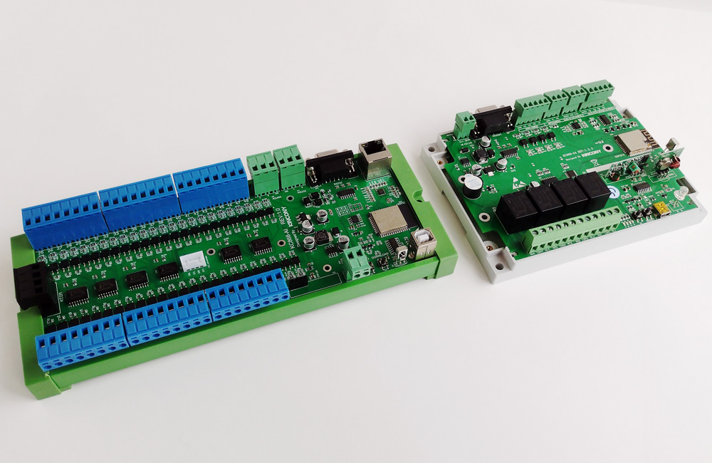
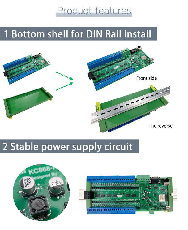
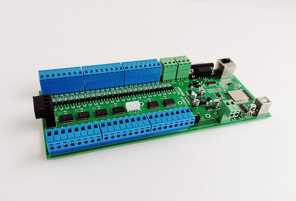
For comparison, here is a photo of the KC868-AI next to the “base” Model KC868-A4 of the entire KC868 controller family. There is nothing to comment on here, everything is visible to the “naked eye”, the only thing I would like to note is that for the huge Kincony controllers, matching cabinets are needed. Kincony KC868-AI will require either a larger cabinet in which it will fit with other modules of automatics, or separate it into a special cabinet and place the automatic circuits in a separate cabinet. From the trace is placed a carrier on the DIN rails. Also existing the holes for mounting on any suitable surface (without DIN-rails).
❯ Circuits
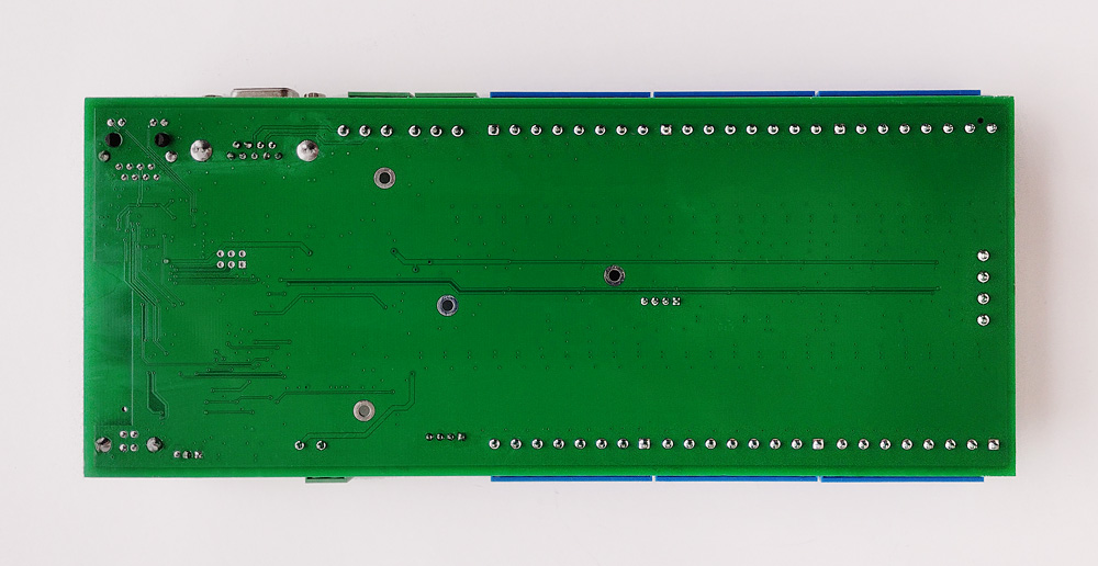
In this article, we will break the tradition of a detailed description of all controller subsystems by introducing appropriate schemes. Kincony uses typical circuit solutions in its products and there is no need in repeating their description from article to article. This review will list and analyze only some of the subsystems characteristic of the KC868-AI model. It’s all in the spirit of Kincony. Attention is on vertical USB and Ethernet connectors and a separate KCOM module. It should also be noted that (with our help) Kincony began installing the connector on the connectivity board without soldering the 433 MHz wireless module and the GPIO ESP32 on a separate connector.
❯ Digital inputs
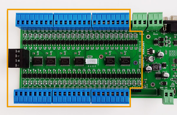
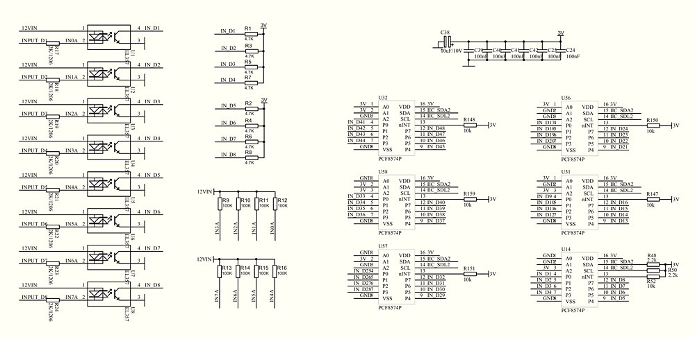
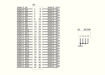
The board has 48 digital opto-isolated “dry contact” inputs on opto couplers EL357, arranged in 6 connectors with 8 inputs each. To ensure their operation in collaboration with ESP32, the KC868-AI uses digital I/O extenders with I2C interface on 6 PCF8574P chips. For clarity and so that the scheme does not clutter, only one of the six blocks of the optocoupler is shown (the others are exactly the same). The PCF8574P connector extenders display all 6. It is important to note the SDA2 /SCL2 designation even though only one I2C interface is used on the board. Moreover, the SCL2 tag is spelled in error (SDL2).
❯ I2C connectors
On the board there is a very useful I2C connector for connecting various additional components. It can be connected, for example, a display, additional sensors and other elements. I2C contact circle diagram:
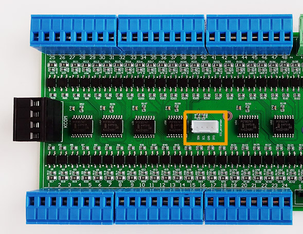
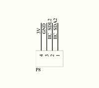
❯ Free GPIO
Another useful add-on is the 4 free to use GPIO on a separate port. They can connect different equipment or arrange analog inputs (which are completely absent on the board). Schematic diagram of connectors with GPIO (34, 35, 36, 39):
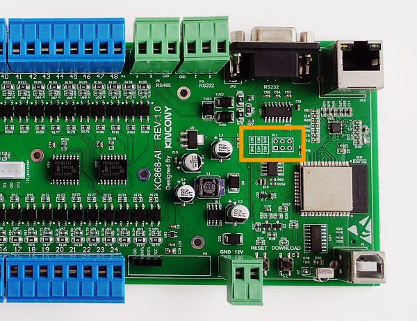
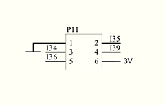
❯ External link scheme
Slightly modified original scheme of connectors and external connections of the KC868-AI controller. The two RS232 connectors are actually one interface that is in two connectors.

❯ Pin layout
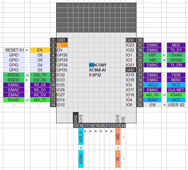
Pinout showing what is and how connected to the ESP32 microcontroller on the KC868-AI board. GPIO2 and GPIO12 do not appear to be connected anywhere and are not included in any way (it could also have been output to the connector with free GPIO).
❯ Programming
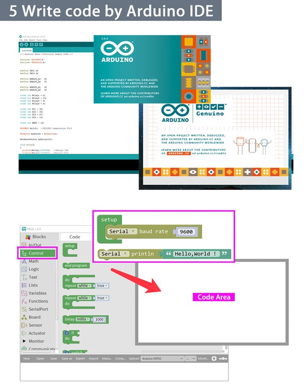
Let’s try now to program KC868-AI and for example create a sketch of obtaining data from its digital inputs. To do this, we will need a library PCF8574_library.
/*
Example KC868-AI DI
*/
#include “Arduino.h”
#include “PCF8574.h”
#define SDA 4
#define SCL 5
PCF8574 pcf_1(0x24, SDA, SCL);
PCF8574 pcf_2(0x25, SDA, SCL);
PCF8574 pcf_3(0x21, SDA, SCL);
PCF8574 pcf_4(0x22, SDA, SCL);
PCF8574 pcf_5(0x26, SDA, SCL);
PCF8574 pcf_6(0x23, SDA, SCL);
null setup() {
Serial start(115200);
Serial.println();
Serial.println(F(“KC868-AI DI example start…”));
for (byte i = 0; and < 8; i++) {pcf_1.pinMode(i, INPUT);}
for (byte i = 0; and < 8; i++) {pcf_2.pinMode(i, INPUT);}
for (byte i = 0; and < 8; i++) {pcf_3.pinMode(i, INPUT);}
for (byte i = 0; and < 8; i++) {pcf_4.pinMode(i, INPUT);}
for (byte i = 0; and < 8; i++) {pcf_5.pinMode(i, INPUT);}
for (byte i = 0; and < 8; i++) {pcf_6.pinMode(i, INPUT);}
Serial.print(“Init pcf 1…” ); if (pcf_1.begin()){Serial.println(“OK”);} else {Serial.println(“Err”);}
Serial.print(“Init pcf 2…” ); if (pcf_2.begin()){Serial.println(“OK”);} else {Serial.println(“Err”);}
Serial.print(“Init pcf 3…” ); if (pcf_3.begin()){Serial.println(“OK”);} else {Serial.println(“Err”);}
Serial.print(“Init pcf 4…” ); if (pcf_4.begin()){Serial.println(“OK”);} else {Serial.println(“Err”);}
Serial.print(“Init pcf 5…” ); if (pcf_5.begin()){Serial.println(“OK”);} else {Serial.println(“Err”);}
Serial.print(“Init pcf 6…” ); if (pcf_6.begin()){Serial.println(“OK”);} else {Serial.println(“Err”);}
delay(1000);
}
void loop() {
Serial.println();
for (byte i = 0; and < 8; i++) {Serial.print(pcf_1.digitalRead(i));} Serial.print(‘ ‘);
for (byte i = 0; and < 8; i++) {Serial.print(pcf_2.digitalRead(i));} Serial.print(‘ ‘);
for (byte i = 0; and < 8; i++) {Serial.print(pcf_3.digitalRead(i));} Serial.print(‘ ‘);
for (byte i = 0; and < 8; i++) {Serial.print(pcf_4.digitalRead(i));} Serial.print(‘ ‘);
for (byte i = 0; and < 8; i++) {Serial.print(pcf_5.digitalRead(i));} Serial.print(‘ ‘);
for (byte i = 0; and < 8; i++) {Serial.print(pcf_6.digitalRead(i));} Serial.print(‘ ‘);
delay(300);
}
Since on the KC868-AI I2C panel, the interface pins are connected to non-standard GPIO 4 and 5, we need to take this point into account in the code and explicitly state them. Please specify the addresses (0x24, 0x25, 0x21, 0x22, 0x26, 0x23) of the PCF8574P CONNECTOR EXTENDER on the I2C bus immediately. Why aren’t the addresses in order? Obviously, in order not to relax and programming does not seem such an easy task to us.
#define SDA 4
#define SCL 5
PCF8574 pcf_1(0x24, SDA, SCL);
PCF8574 pcf_2(0x25, SDA, SCL);
PCF8574 pcf_3(0x21, SDA, SCL);
PCF8574 pcf_4(0x22, SDA, SCL);
PCF8574 pcf_5(0x26, SDA, SCL);
PCF8574 pcf_6(0x23, SDA, SCL);
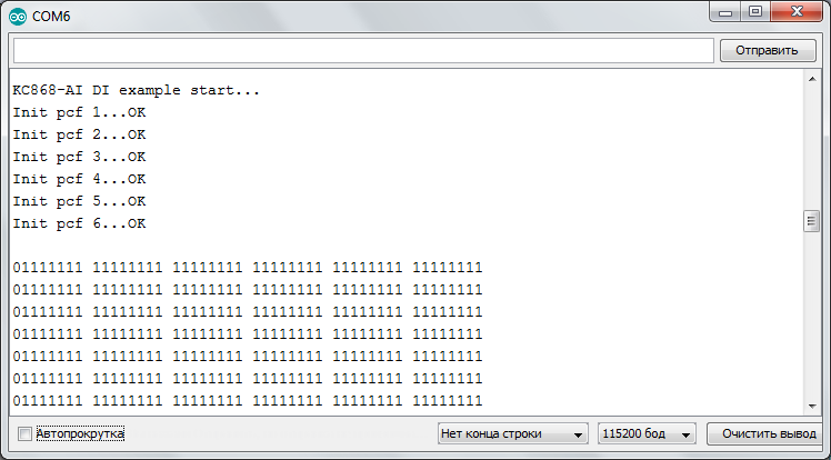
Now everything is clear: we treat the expansion lines as inputs and in the loop print the matrix of all 48 digital inputs of the KC868-AI (pay attention to the zero in the first position of each line – it is the first input closed to KCOM).
❯ Conclusion
Kincony has released another excellent controller for DIY and even industrial automation – everything is simple and understandable to program – if your task fits its characteristics, you can safely use it to carry out your project.


