
Here we came across a product called “ESP32 Tuya IoT adapter”, you can appreciate the originality of its appearance from the photo above. On the other hand, the name contains ESP32, and as you know, if the device contains ESP32, then this is undoubtedly a great thing, so I decided to explore its device. Well, Tuya intrigued me too, it was interesting to join the advanced ideas of Chinese smart home technology.
What is Tuya
In short, Tuya is a “smart (AI) Chinese cloud” specifically designed to serve IoT devices and build a (proverbial) “smart home.” That cloud is not simple, but refined and technologically advanced, it has developed an API, a system of standards and even specialized chips (microcontrollers). According to information from the Internet, Tuya is an incredibly popular thing, there are many users and developers in its ecosystem, there are a large number of ready-made devices compatible with Tuya on the market (sensors, sockets, etc.). Of course, there is an application for smartphones, a website, detailed internet documentation, a Youtube channel, a library (SDK) for Arduino, etc. With such hype around this technology. In general, Tuya seems to be a pretty promising technology that deserves at least a cursory look to get acquainted with it, which we will do (partially) in this and (more complete) subsequent articles .
ESP32 Tuya IoT Adapter
ESP32 Tuya IoT Adapter is a solution for connecting and adding Tuya cloud (ecosystem) capabilities to your system (smart home). On the one hand it has RS232 and RS485 interfaces, and on the other hand it has communication with the Tuya cloud. Initially, the ESP32 Tuya IoT adapter was designed to work with fairly advanced Kincony controllers, but no one bothers to connect this adapter via an RS232 or RS485 interface to your favorite smart home controller. In other words, the ESP32 Tuya IoT adapter is a solution to quickly and easily add the operation of the Tuya ecosystem to your smart home (or any other IoT system). The operation of the adapter with Tuya cloud is provided by a specialized CBU-IPEX chip, which we will discuss in detail below. Everyone’s favorite ESP32 is also on board (where without it), which turns a modest “adapter” into a much more functional device, actually a full-fledged IoT controller, the functionality of which depends only on your imagination and programming skills. The ESP32 Tuya IoT adapter contains:
- Microcontroller ESP32-WROOM-32UE
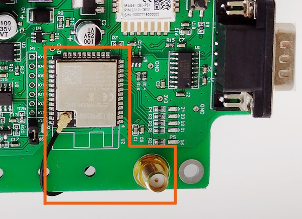
- SMA connector and antenna for ESP32
- DOWNLOAD and RESET buttons
- 7 free GPIO ESP32
- Rs232/RS485 mode jumper
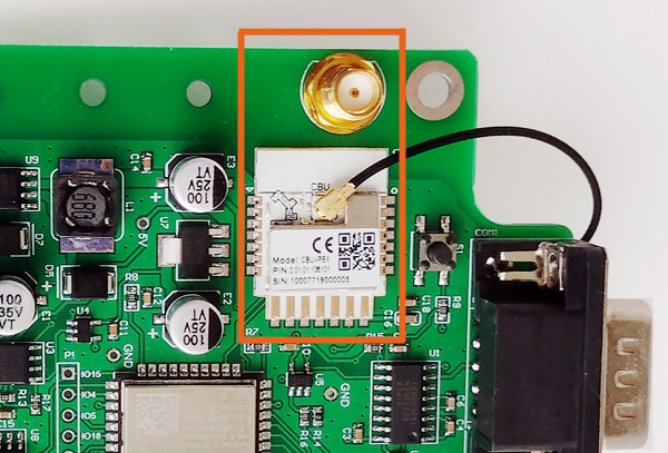
- Tuya chip CBU-IPEX
- SMA connector and antenna for CBU-IPEX
- S1 button
- LEDs with 5 indicators
- RS232 port
- RS485 port
- USB Type-C port
- Connector and power 9-24 V
Appearance and mounting
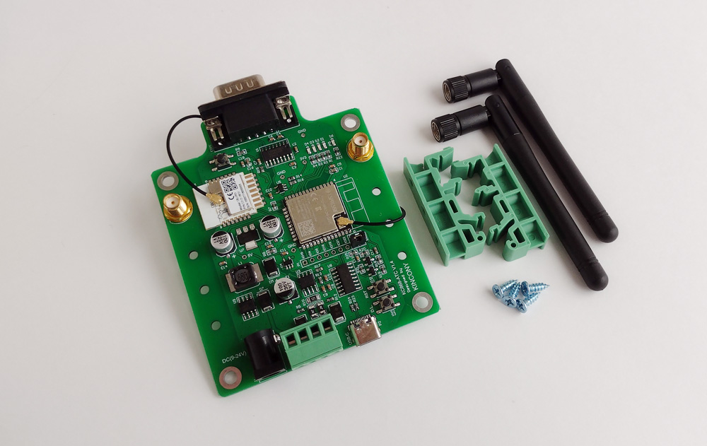
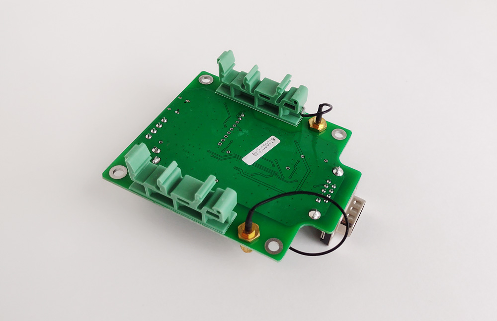
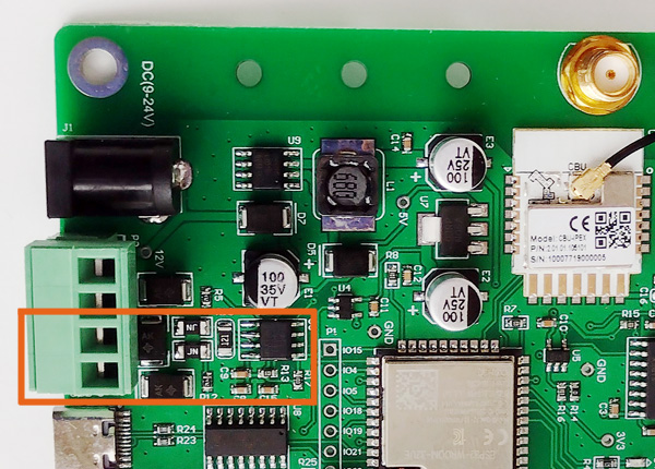
The kit consists of an ESP32 Tuya IoT adapter panel, two antennas and two brackets for DIN rails. The board can be installed on the DIN rail, fixed using appropriate holes or even simply “hang” on the RS232 connector (in this case you need to make sure that there are no mechanical stresses, otherwise the connector can be damaged, so it is not recommended). View of the adapter from the back, with mounts installed on the DIN rail. SMA connectors are connected to controllers using special cables and if necessary, these cables can be extended and antennas can be moved outside the communication cabinet.
Circuit design
Top view of the ESP32 Tuya IoT adapter. On the board you can see the alternative name of the adapter – KC868-ATC. On the back of the board, traditionally for Kincony, it does not contain any electronic components.


Power supply
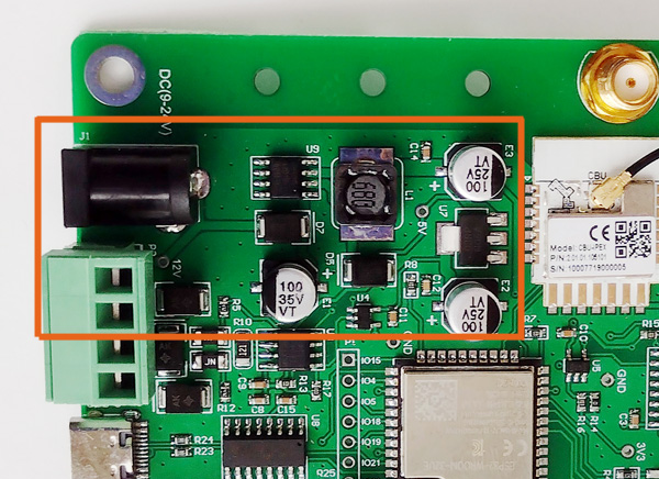
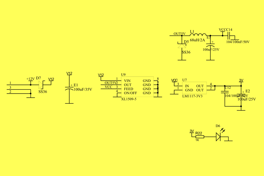
The power subsystem consists of an XL1509-5 step-down DC-DC converter, a 12 V and 5 V voltage generation chip and a linear regulator LM117-3V3 to produce a voltage of 3.3 V. The adapter can be powered by a voltage of 9-24 V or through a round connector “for Arduino”, or through an adjacentand connector.
Schematic diagram of the power subsystem
ESP32
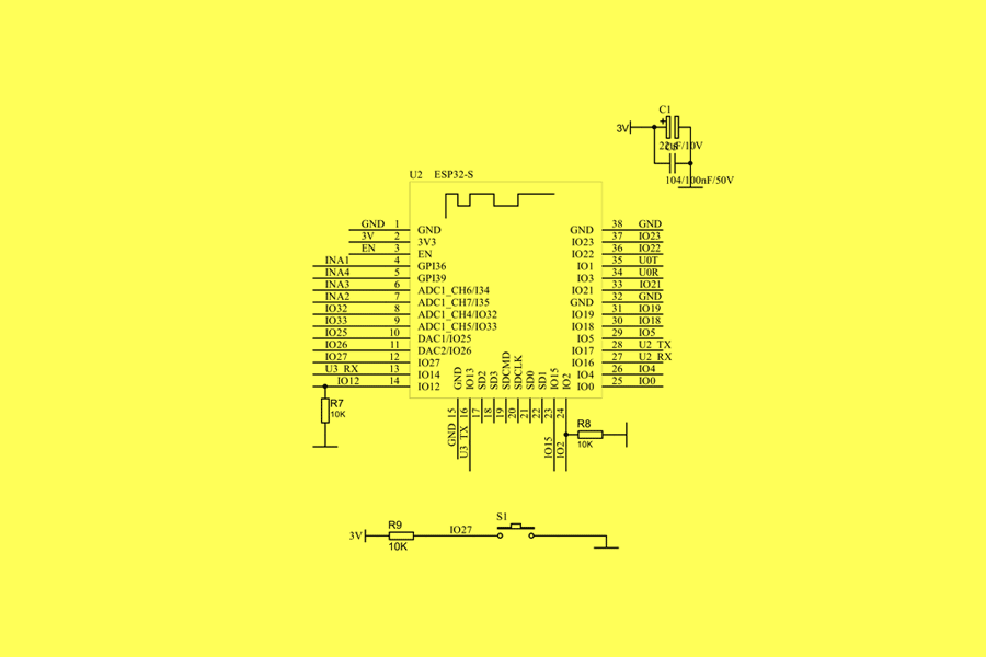
The ESP32 Tuya IoT adapter contains the ESP32-WROOM-32UE module as the “brain” of the system and a connecting hub between its elements. On the one hand, the Tuya CBU-IPEX chip is connected to esp32 (via UART3 interface), and on the other hand, via UART2, “parallel” RS232 and RS485 interfaces. By “parallelism” RS232 and RS485 interfaces we mean their simultaneous physical connection to ESP32 within the adapter and software configuration and selecting one of the interfaces in the code (this assumes that you can work with RS232 or RS485, but not with both at the same time ). In addition to the connection between the parts of the adapter, ESP32 can solve many more tasks: web interface, receive and send data via Wi-Fi connection and use as a Wi-Fi-Tuya bridge, use free GpIOs displayed on the board, processing information, etc. In other words, you can make a very, very advanced device from the ESP32 Tuya IoT adapter.
Schematic diagram and core pinout (ESP32) controller:
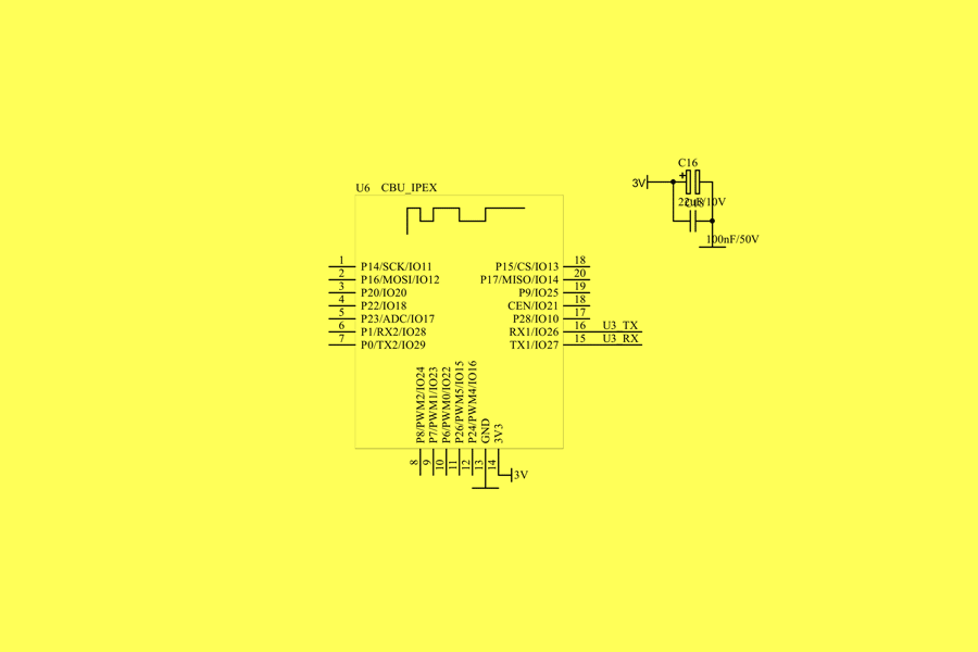
Tuya CBU-IPEX
Perhaps one can’t say better about CBU-IPEX than what’s written in the official documentation, quote:
CBU-IPEX is a built-in low-power Wi-Fi module developed by Tuya. It consists of a highly integrated BK7231N RF chip and several peripherals, and not only supports ap and STA two-network connection mode, but also supports Bluetooth LE network connection mode. CBU-IPEX is built-in with a 32-bit MCU with speeds of up to 120 MHz, 2Mbyte flash memory, and 256-KB RAM, to support Tuya IoT connection in the cloud. The MCU’s specially extended signal processing instructions can effectively implement audio coding and decoding. In addition, it has rich peripherals, such as PWM, UART and SPI. Five 32-bit PWM output makes the chip very suitable for high-quality LED control.
In simpler words: CBU-IPEX is a specialized Tuya module that has wireless interfaces and contains firmware inside that supports Functions specific to Tuya both for working with connected equipment and for Tuya cloud (platform itself). For us, this means that we can transfer the corresponding firmware to ESP32, and our system will “magically” support Tuya, or we can download the SDK (library) for Arduino and create firmware that supports CBU-IPEX (Tuya) for ESP32 independently. Analysis of how to work with Tuya and how to create such firmware is definitely a topic for a separate article (and most likely not one).
Schematic diagram of the Tuya CBU-IPEX subsystem:
USB-UART
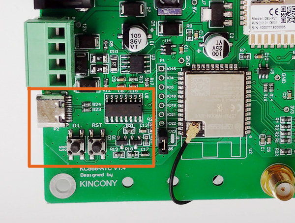
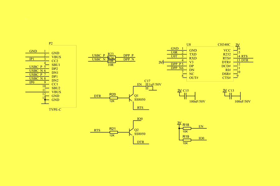
The USB-UART subsystem for communication with the computer and programming is implemented on the CH340C chip and has a USB Type-C port. There are also two buttons here – RESET and DOWNLOAD, labeled as “RST” and “DL”.
Usb-UART subsystem schematic diagram:
RS232 interface
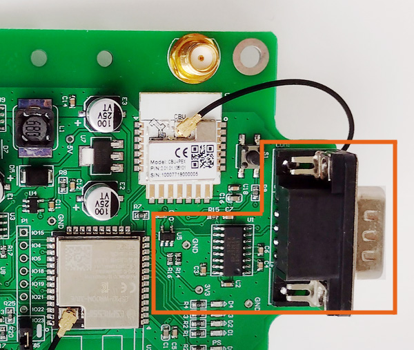
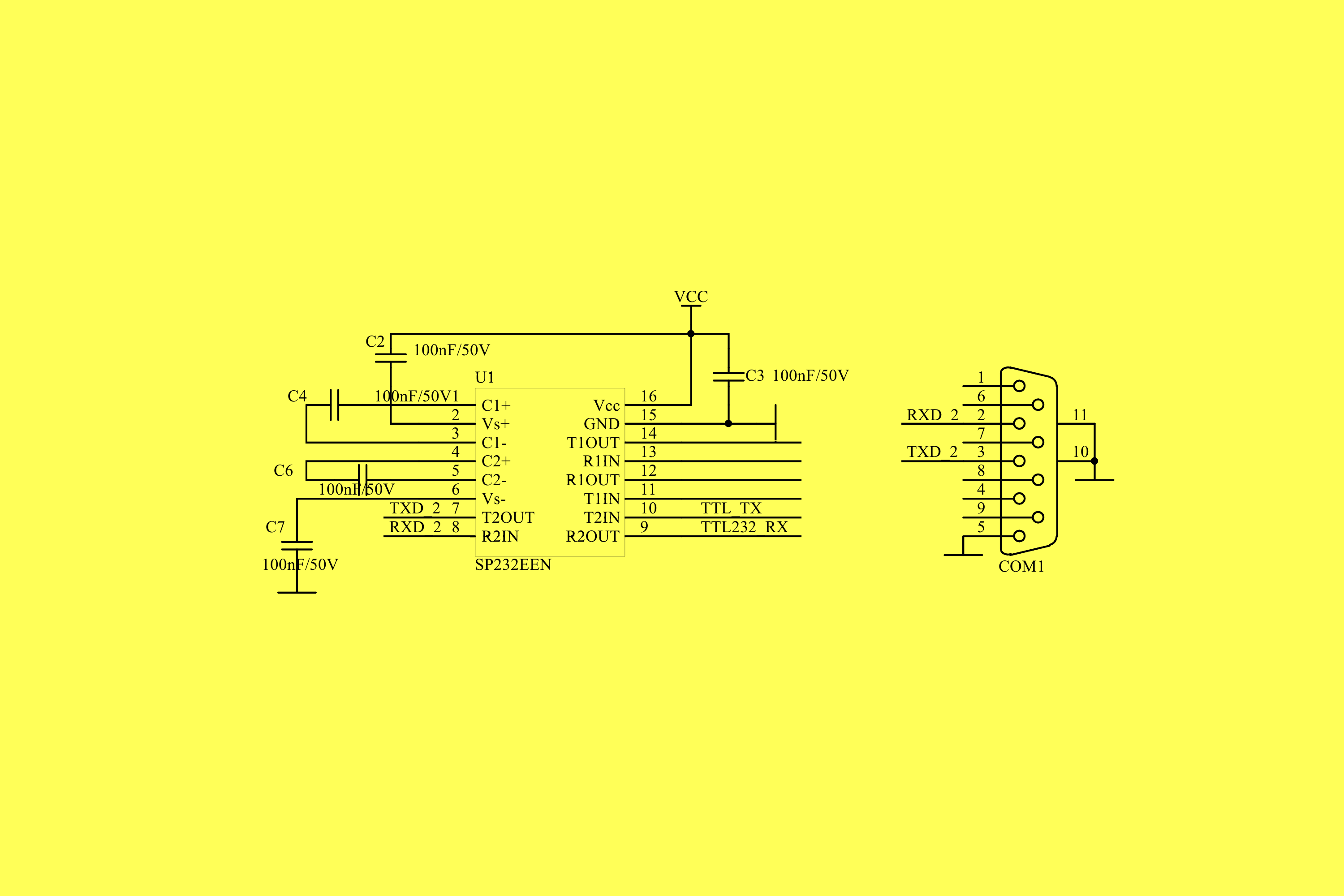
The RS232 interface is implemented on the SP232EEN chip, which is connected to the 74LVC1G08 and 74AHCT1G125 buffers (see RS485 diagram below) which, in turn, are connected to ESP32 via the UART2 interface (GPIO16 and GPIO17).
Schematic diagram of RS232 interface subsystem:
RS485 interface
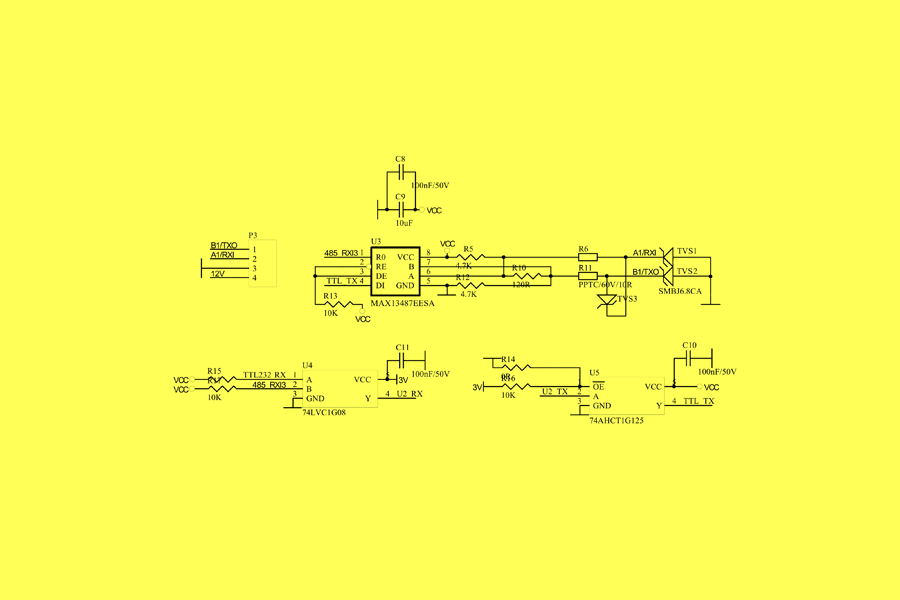
The Rs485 interface is implemented on the MAX13487EESA chip, which is also connected to the 74LVC1G08 and 74AHCT1G125 buffers and is “parallel” to the RS232 (see above). The choice of working with one or another interface is made programmatically (this will be discussed below).
Schematic diagram of RS485 interface subsystem:
Indicator LEDs
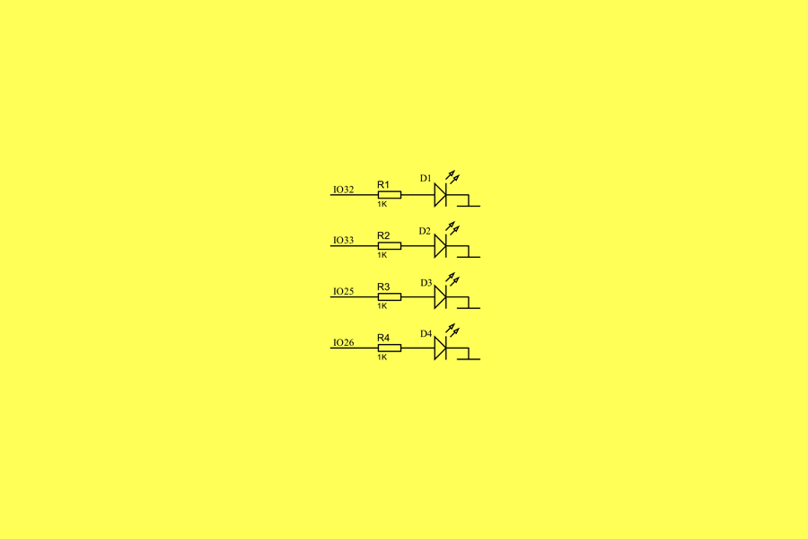
On the side of the panel there is a block of 5 indicator LEDs. Of these, one indicates the presence of a power supply voltage (D6), and the others are connected to ESP32 and are freely programmed.
Schematic diagram of the LED indicator subsystem:

Free GpIOs and RS232/RS485 bypass (jumper)
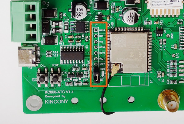
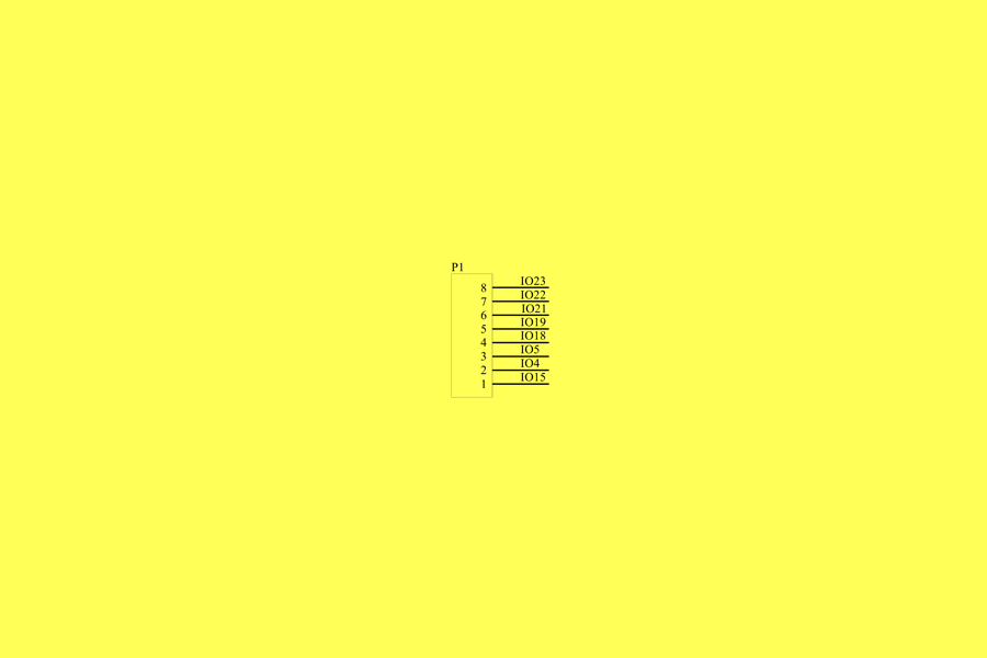
Kincony listened to our wishes and began enabling free GPIOs to free use. This simple action allows you to significantly expand the functionality of the ESP32 Tuya IoT adapter and connect the accessories you need to it. The board has 7 free GPIO and one Jumper GPIO23-GND for programming determine the RS232/RS485 mode.
Schematic diagram of a free GPIO subsystem:
Connection diagram
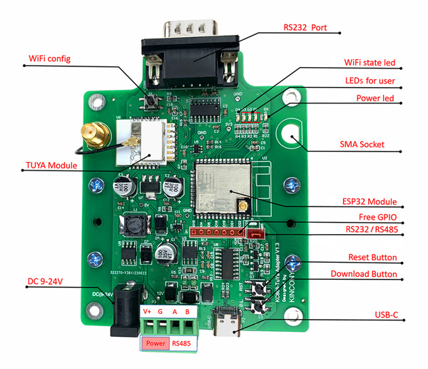
Below is an official diagram of connectors, components and connections made by Kincony. Programm defined things, for example, the allocation of INDICATOR LEDs, are given conditionally – you can redefine them in your sketch.
Pinout
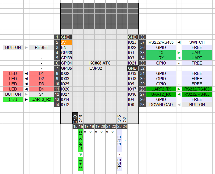
A little more clarity on the ESP32 Tuya IoT adapter can be provided with a pinout below. Only GPIO2, 34, 35, 36, 39 remained unused.
Conclusion
With the device, purpose and assemblies of the ESP32 Tuya IoT adapter everything is more or less clear, it remains only to understand its programming and work with Tuya Cloud, but this, as they say, is a completely different story … (Stay tuned.)


