Hi. I'm planning to connect the protection fuses before the relays, and not after as shown in the tutorials. This way I would be able to have one fuse for a group of channels (for example all lights in an area/room).
I do so because of 2 reasons: (1) Such connection is viable in my house because, for example, the wiring to all the lights for the living room is being passed through a single connections-box. Using wiring of different protected circuits in the same box is prohibited by law in my country. (2) Grouping circuits use fewer fuses and save space in the power distribution box.
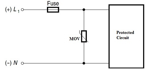
Can such a connection cause any problem? The relays module has a varistor per channel, and I read online that a fuse has to be connected over the circuit with the varistor. My question regards the location of the fuse. Schematically, I'm asking whether it is critical to have the fuse on the closed-circuit between the varistor and the device (like you suggest in your tutorials), or is it also fine to connect the fuse to the feeding phase (leaving the closed circuit between the varistor and the consumption end device without any protection, as shown in the diagram below). I don't really understand the theory behind the varistor's operation, so I don't know if it may be a problem leaving it with the device in a closed circuit without protection on it.

Thanks for the help!
I do so because of 2 reasons: (1) Such connection is viable in my house because, for example, the wiring to all the lights for the living room is being passed through a single connections-box. Using wiring of different protected circuits in the same box is prohibited by law in my country. (2) Grouping circuits use fewer fuses and save space in the power distribution box.
Can such a connection cause any problem? The relays module has a varistor per channel, and I read online that a fuse has to be connected over the circuit with the varistor. My question regards the location of the fuse. Schematically, I'm asking whether it is critical to have the fuse on the closed-circuit between the varistor and the device (like you suggest in your tutorials), or is it also fine to connect the fuse to the feeding phase (leaving the closed circuit between the varistor and the consumption end device without any protection, as shown in the diagram below). I don't really understand the theory behind the varistor's operation, so I don't know if it may be a problem leaving it with the device in a closed circuit without protection on it.
Thanks for the help!


