01-04-2023, 01:17 AM
1. here is GPIO pins define for KC868-A6:
https://www.kincony.com/forum/showthread.php?tid=1962
2. I understand I2C and assume the display and external connector are wired to GPIO4 and GPIO15 and there are no other access points to that bus. Is this correct?
--> Yes, you are right, extend by this two wire SDA and SCL.
3. I understand the PCF8574 expander/multiplexer and the configuration with the 6 relays and the 6 DI ports that can be configured as INPUT/OUTPUT and through rules you can map inputs to drive the relays, IS THIS CORRECT?
--> PCF8574 can define every PIN for INPUT or OUTPUT mode, but our board input and output have different circuit, so input only define for INPUT, output only define for OUTPUT. you can't use INPUT for OUTPUT.
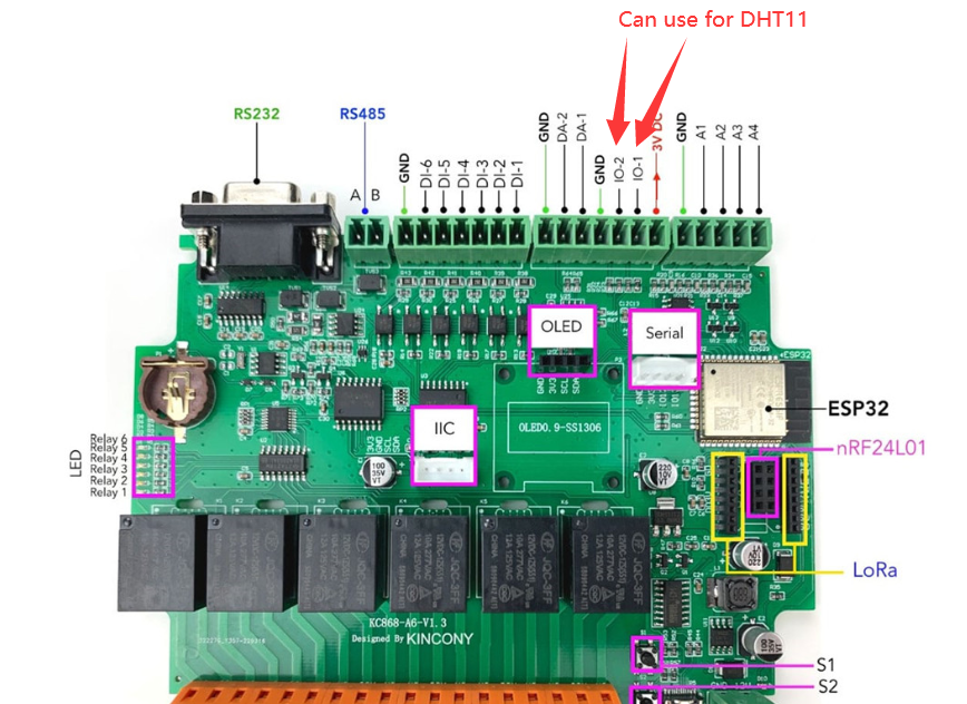
4. here is photo have IO-1 and IO-2 , these two pins can use for DHT11 or DS18B20 sensor, it have pull up resistance on the PCB.

DS18B20/DHT11/DHT21/LED strip -1: 32 (IO-1)
DS18B20/DHT11/DHT21/LED strip -2: 33 (IO-2)
these are IO1 and IO2 GPIO number, they are GPIO32, GPIO33
5. please see this link about pin define, all have listed:
https://www.kincony.com/forum/showthread.php?tid=1962
6. KC868-A6 tasmota firmware you can see this link:
https://www.kincony.com/forum/showthread.php?tid=2405
https://www.kincony.com/forum/showthread.php?tid=1962
2. I understand I2C and assume the display and external connector are wired to GPIO4 and GPIO15 and there are no other access points to that bus. Is this correct?
--> Yes, you are right, extend by this two wire SDA and SCL.
3. I understand the PCF8574 expander/multiplexer and the configuration with the 6 relays and the 6 DI ports that can be configured as INPUT/OUTPUT and through rules you can map inputs to drive the relays, IS THIS CORRECT?
--> PCF8574 can define every PIN for INPUT or OUTPUT mode, but our board input and output have different circuit, so input only define for INPUT, output only define for OUTPUT. you can't use INPUT for OUTPUT.
4. here is photo have IO-1 and IO-2 , these two pins can use for DHT11 or DS18B20 sensor, it have pull up resistance on the PCB.
DS18B20/DHT11/DHT21/LED strip -1: 32 (IO-1)
DS18B20/DHT11/DHT21/LED strip -2: 33 (IO-2)
these are IO1 and IO2 GPIO number, they are GPIO32, GPIO33
5. please see this link about pin define, all have listed:
https://www.kincony.com/forum/showthread.php?tid=1962
6. KC868-A6 tasmota firmware you can see this link:
https://www.kincony.com/forum/showthread.php?tid=2405
YouTube: https://www.youtube.com/c/KinCony
Online Store: https://shop.kincony.com
Alibaba Store: https://kincony.en.alibaba.com/
Online Store: https://shop.kincony.com
Alibaba Store: https://kincony.en.alibaba.com/


