Posts: 291
Threads: 234
Joined: Jan 2021
 01-05-2022, 08:27 AM
(This post was last modified: 04-27-2022, 06:54 AM by KinCony Support.)
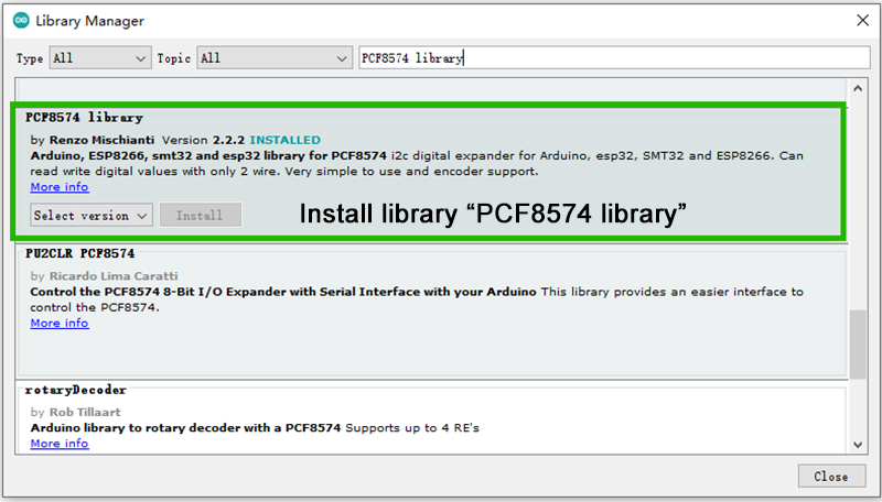
Code 7: //The demo code is PCF8574-DO You can copy the code to your Arduino IDE.
Code: #include "Arduino.h"
#include "PCF8574.h"
// Set i2c address
PCF8574 pcf8574_1(0x24,4,5);
PCF8574 pcf8574_2(0x25,4,5);
void setup()
{
Serial.begin(115200);
pcf8574_1.pinMode(P0, OUTPUT);
pcf8574_1.pinMode(P1, OUTPUT);
pcf8574_1.pinMode(P2, OUTPUT);
pcf8574_1.pinMode(P3, OUTPUT);
pcf8574_1.pinMode(P4, OUTPUT);
pcf8574_1.pinMode(P5, OUTPUT);
pcf8574_1.pinMode(P6, OUTPUT);
pcf8574_1.pinMode(P7, OUTPUT);
pcf8574_2.pinMode(P0, OUTPUT);
pcf8574_2.pinMode(P1, OUTPUT);
pcf8574_2.pinMode(P2, OUTPUT);
pcf8574_2.pinMode(P3, OUTPUT);
pcf8574_2.pinMode(P4, OUTPUT);
pcf8574_2.pinMode(P5, OUTPUT);
pcf8574_2.pinMode(P6, OUTPUT);
pcf8574_2.pinMode(P7, OUTPUT);
Serial.print("Init pcf8574_1...");
if (pcf8574_1.begin()){
Serial.println("PCF8574_1_OK");
}else{
Serial.println("PCF8574_1_KO");
}
Serial.print("Init pcf8574_2...");
if (pcf8574_2.begin()){
Serial.println("PCF8574_2_OK");
}else{
Serial.println("PCF8574_2_KO");
}
}
void loop()
{
pcf8574_1.digitalWrite(P7, LOW);
delay(1000);
pcf8574_1.digitalWrite(P7, HIGH);
delay(1000);
pcf8574_2.digitalWrite(P7, LOW);
delay(1000);
pcf8574_2.digitalWrite(P7, HIGH);
delay(1000);
}


Posts: 6,313
Threads: 808
Joined: Oct 2020
Reputation:
154
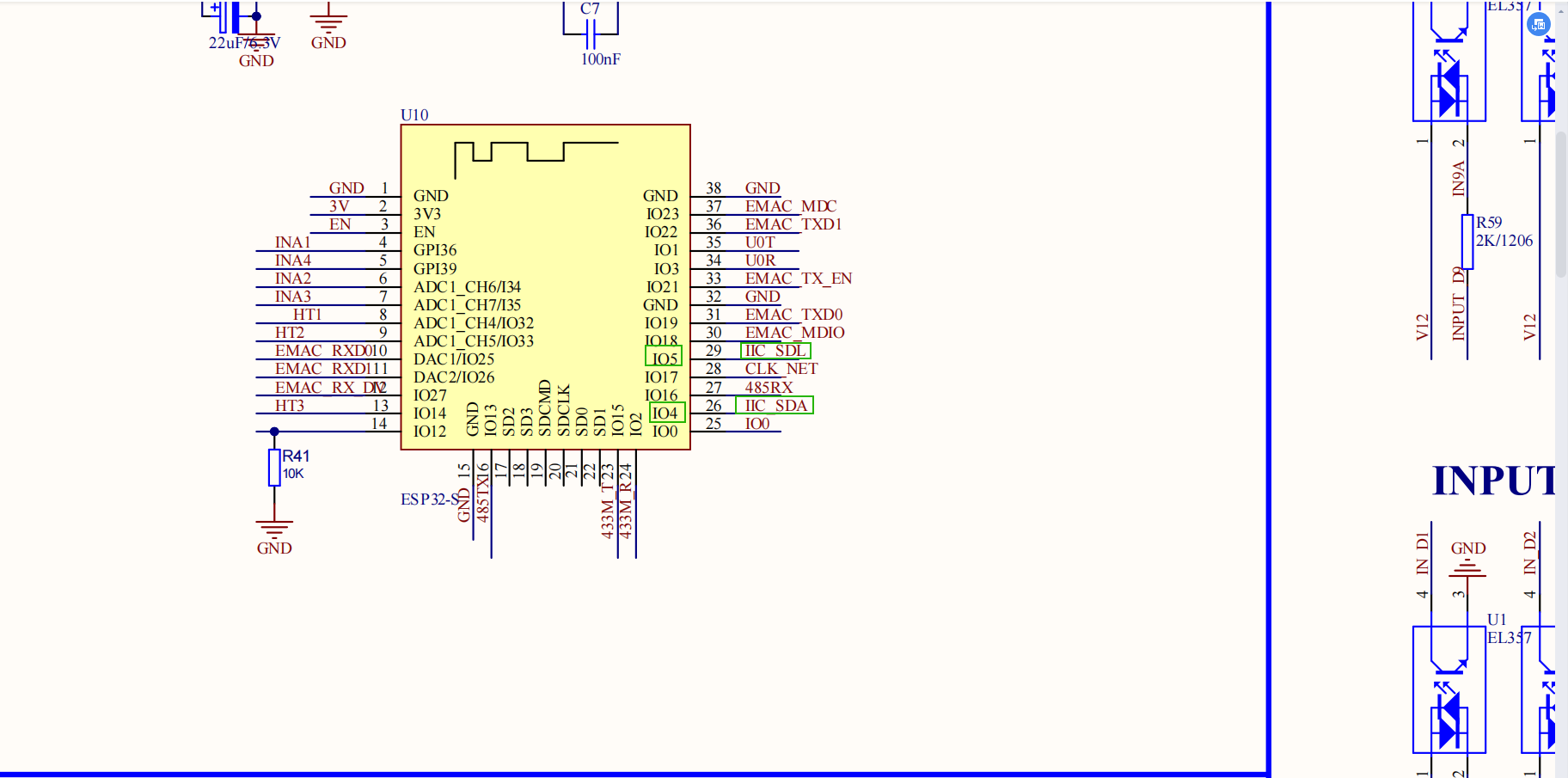
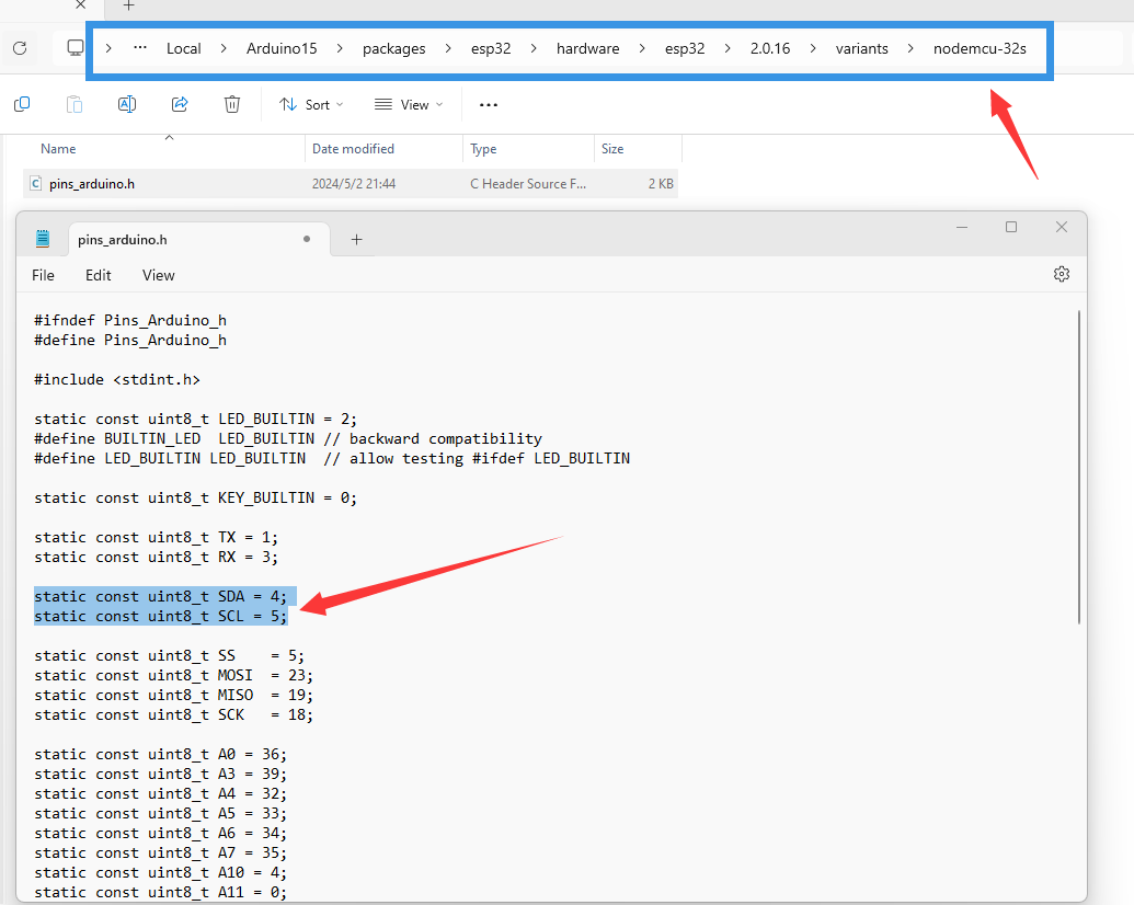
i2c bus pins setting.

Posts: 4
Threads: 1
Joined: Jun 2024
Reputation:
0
Running this code, the relays are not able on/ off. Measure the voltage from opto coupler. they are just change from 3.3V to 2.1V (should be 0V). Please help.
Posts: 6,313
Threads: 808
Joined: Oct 2020
Reputation:
154
maybe you have not connect dc12v with these "INPUT" terminal. take a photo how you wire cable.

Posts: 4
Threads: 1
Joined: Jun 2024
Reputation:
0
Sorry, I was wrong. the 1.2V is good for couplers. The question is now move to where are LO0 and LO1 come from? Measuring the pin#6 and pin#4 of couplers, the voltage is not change when couplers is on or off.
Posts: 6,313
Threads: 808
Joined: Oct 2020
Reputation:
154
take a photo how you wire cable.
Posts: 4
Threads: 1
Joined: Jun 2024
Reputation:
0
You're right. we didn't connect 12V to output terminals yet. And board is working now. thanks!!!!
Posts: 3
Threads: 0
Joined: Nov 2024
Reputation:
0
I've got a16 board and downloaded latest arduino IDE with esp board support rev 3.0.5. The difference is that pinout is a bit modified e.g. SDA/SDL are 21 & 22 not 4 & 5. Should use older version e.g. rev. 2.0.16? Also there is no definition of P0..P7, I made modification od example code as follow to get it compiled:
Code: #include "Arduino.h"
#include "Adafruit_PCF8574.h"
static const uint8_t P0 = 0;
static const uint8_t P1 = 1;
static const uint8_t P2 = 2;
static const uint8_t P3 = 3;
static const uint8_t P4 = 4;
static const uint8_t P5 = 5;
static const uint8_t P6 = 6;
static const uint8_t P7 = 7;
// Set i2c address
Adafruit_PCF8574 pcf8574_1;//(0x24,4,5);
Adafruit_PCF8574 pcf8574_2;//(0x25,4,5);
void setup()
{
Serial.begin(115200);
pcf8574_1.pinMode(P0, OUTPUT);
pcf8574_1.pinMode(P1, OUTPUT);
pcf8574_1.pinMode(P2, OUTPUT);
pcf8574_1.pinMode(P3, OUTPUT);
pcf8574_1.pinMode(P4, OUTPUT);
pcf8574_1.pinMode(P5, OUTPUT);
pcf8574_1.pinMode(P6, OUTPUT);
pcf8574_1.pinMode(P7, OUTPUT);
pcf8574_2.pinMode(P0, OUTPUT);
pcf8574_2.pinMode(P1, OUTPUT);
pcf8574_2.pinMode(P2, OUTPUT);
pcf8574_2.pinMode(P3, OUTPUT);
pcf8574_2.pinMode(P4, OUTPUT);
pcf8574_2.pinMode(P5, OUTPUT);
pcf8574_2.pinMode(P6, OUTPUT);
pcf8574_2.pinMode(P7, OUTPUT);
Wire.begin(21, 22);
Serial.print("Init pcf8574_1...");
if (pcf8574_1.begin(0x24, &Wire)){
Serial.println("PCF8574_1_OK");
}else{
Serial.println("PCF8574_1_KO");
}
Serial.print("Init pcf8574_2...");
if (pcf8574_2.begin(0x25, &Wire)){
Serial.println("PCF8574_2_OK");
}else{
Serial.println("PCF8574_2_KO");
}
}
void loop()
{
pcf8574_1.digitalWrite(P7, LOW);
delay(1000);
pcf8574_1.digitalWrite(P7, HIGH);
delay(1000);
pcf8574_2.digitalWrite(P7, LOW);
delay(1000);
pcf8574_2.digitalWrite(P7, HIGH);
delay(1000);
}
Posts: 6,313
Threads: 808
Joined: Oct 2020
Reputation:
154
just do as our sample code's I2C bus pin define.
Posts: 3
Threads: 0
Joined: Nov 2024
Reputation:
0
(11-07-2024, 11:52 AM)admin Wrote: just do as our sample code's I2C bus pin define.
I did set pint to 4/5 and modified your example to get it up and running, maybe someone else will re-use it as original code is not working - at lest for myself)
Code: #include "Arduino.h"
#include "Adafruit_PCF8574.h"
static const uint8_t P0 = 0;
static const uint8_t P1 = 1;
static const uint8_t P2 = 2;
static const uint8_t P3 = 3;
static const uint8_t P4 = 4;
static const uint8_t P5 = 5;
static const uint8_t P6 = 6;
static const uint8_t P7 = 7;
static const uint8_t PIN_UART_RX = 3;
static const uint8_t PIN_UART_TX = 1;
static const uint8_t PIN_SDA = 4;
static const uint8_t PIN_SCL = 5;
// Set i2c address
Adafruit_PCF8574 pcf8574_1;//(0x24,4,5);
Adafruit_PCF8574 pcf8574_2;//(0x25,4,5);
TwoWire i2c = TwoWire(0);
void setup()
{
Serial.setPins(PIN_UART_RX, PIN_UART_TX);
Serial.begin(9600);
delay(1000);
i2c.begin(PIN_SDA, PIN_SCL);
Serial.print("Init pcf8574_1...");
if (pcf8574_1.begin(0x24, &i2c)){
Serial.println("PCF8574_1_OK\n");
}else{
Serial.println("PCF8574_1_KO");
}
Serial.print("Init pcf8574_2...");
if (pcf8574_2.begin(0x25, &i2c)){
Serial.println("PCF8574_2_OK");
}else{
Serial.println("PCF8574_2_KO");
}
pcf8574_1.pinMode(P0, OUTPUT);
pcf8574_1.pinMode(P1, OUTPUT);
pcf8574_1.pinMode(P2, OUTPUT);
pcf8574_1.pinMode(P3, OUTPUT);
pcf8574_1.pinMode(P4, OUTPUT);
pcf8574_1.pinMode(P5, OUTPUT);
pcf8574_1.pinMode(P6, OUTPUT);
pcf8574_1.pinMode(P7, OUTPUT);
pcf8574_2.pinMode(P0, OUTPUT);
pcf8574_2.pinMode(P1, OUTPUT);
pcf8574_2.pinMode(P2, OUTPUT);
pcf8574_2.pinMode(P3, OUTPUT);
pcf8574_2.pinMode(P4, OUTPUT);
pcf8574_2.pinMode(P5, OUTPUT);
pcf8574_2.pinMode(P6, OUTPUT);
pcf8574_2.pinMode(P7, OUTPUT);
}
void loop()
{
pcf8574_1.digitalWrite(P7, LOW);
delay(1000);
pcf8574_1.digitalWrite(P7, HIGH);
delay(1000);
pcf8574_2.digitalWrite(P7, LOW);
delay(1000);
pcf8574_2.digitalWrite(P7, HIGH);
delay(1000);
}
|


