09-27-2022, 05:34 AM
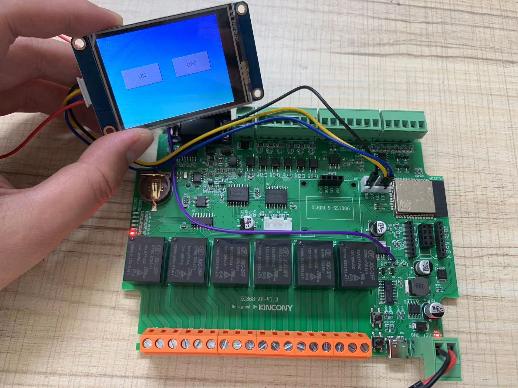
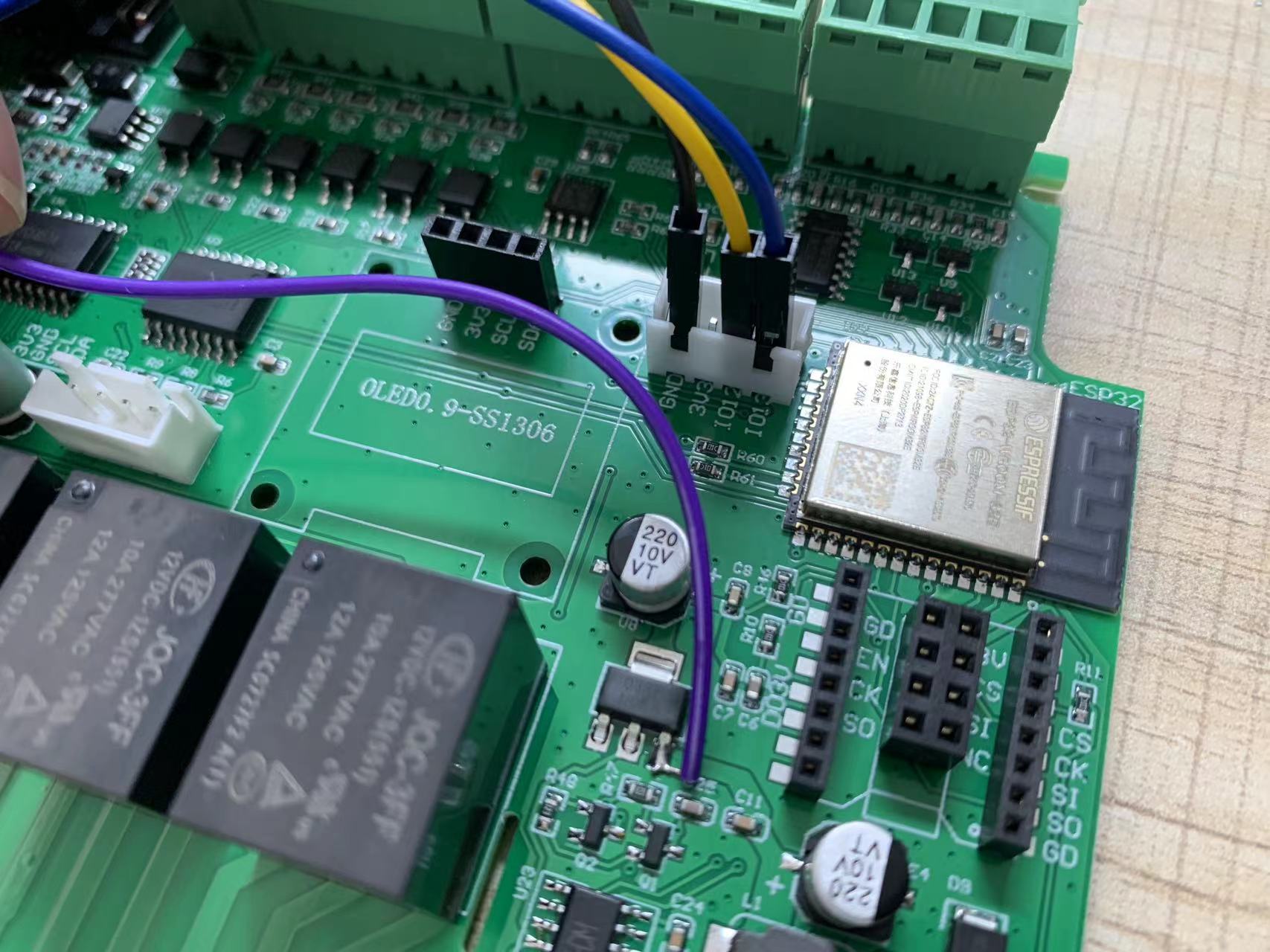
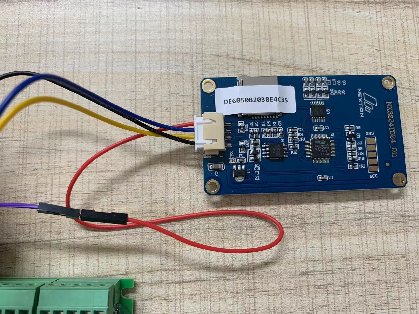
i have used on board extend serial port. actually use want to use VCC,GND,RXD,TXD for Nextion display.
define RXD:GPIO13 TXD:GPIO12 by ESP32
weld Vcc 5V from LM1117 output pin.
here are some photos:


This just a simplest demo, use Nextion display two buttons, press button-one will send 'a' by serial port, press button-two will send 'b' by serial port.
when KC868-A4 received 'a' will turn ON relay1, when received 'b' will turn OFF relay1.
firstly create two buttons UI by Nextion Editor PC software:
![[Image: attachment.php?aid=1429]](https://www.kincony.com/forum/attachment.php?aid=1429)
![[Image: attachment.php?aid=1430]](https://www.kincony.com/forum/attachment.php?aid=1430)
here is firmware BIN file, you can download to KC868-A4 ESP32 directly to use:
 nextion_KC868-A6.ino.nodemcu-32s.zip (Size: 108.86 KB / Downloads: 293)
here are source code:
define RXD:GPIO13 TXD:GPIO12 by ESP32
weld Vcc 5V from LM1117 output pin.
here are some photos:
This just a simplest demo, use Nextion display two buttons, press button-one will send 'a' by serial port, press button-two will send 'b' by serial port.
when KC868-A4 received 'a' will turn ON relay1, when received 'b' will turn OFF relay1.
firstly create two buttons UI by Nextion Editor PC software:
here is firmware BIN file, you can download to KC868-A4 ESP32 directly to use:
 nextion_KC868-A6.ino.nodemcu-32s.zip (Size: 108.86 KB / Downloads: 293)
here are source code:
Code:
#include "PCF8574.h"


String indata="";

String val="";


// Set i2c address

PCF8574 pcf8574(0x24);


void setup() {


  Serial1.begin(9600,SERIAL_8N1,13,12);

  Serial.begin(9600);

  pcf8574.pinMode(P0, OUTPUT);

  pcf8574.pinMode(P1, OUTPUT);

  pcf8574.pinMode(P2, OUTPUT);

  pcf8574.pinMode(P3, OUTPUT);

  pcf8574.pinMode(P4, OUTPUT);

  pcf8574.pinMode(P5, OUTPUT);


  Serial.print("Init pcf8574...");

  if (pcf8574.begin()){

    Serial.println("OK");

  }else{

    Serial.println("KO");

  }

  pcf8574.digitalWrite(P0, HIGH);

  pcf8574.digitalWrite(P1, HIGH);

  pcf8574.digitalWrite(P2, HIGH);

  pcf8574.digitalWrite(P3, HIGH);

  pcf8574.digitalWrite(P4, HIGH);

  pcf8574.digitalWrite(P5, HIGH);

}


void loop() {

  while(Serial1.available()>0)

  {

    indata+=char(Serial1.read());

    delay(2);

    if(Serial1.available()<=0)

     {

        Serial.println(indata);

     }

  }

  if(indata.length()>0)

  {

     val=indata;

     if(val=="a")

       {

         pcf8574.digitalWrite(P0, LOW);

         Serial.println("Relay1-ON OK!");

       }

     else if(val=="b")

      {

         pcf8574.digitalWrite(P0, HIGH);

         Serial.println("Relay1-OFF OK!");

      }

  }

  indata="";

}


