Posts: 6
Threads: 1
Joined: Sep 2023
Reputation:
0
09-13-2023, 04:59 PM
(This post was last modified: 09-14-2023, 01:06 PM by sure.)
I've received an m16v2 today.
I've have flashed it with esphome with the provided yaml file you've provided. After that, the onboard LCD screen began working.
I've included the zmpt101b/ folder and have confirmed that this code is getting included in and compiled in the binary firmware.
Unfortunately, I'm not able to get any voltage readings from the zmpt101b chips. I've tried voltage_1 & voltage_3. Neither return any values.
I'm confirming that nothing is sent not only via the LCD display (which defaults to voltage_1), but also in Home Assistant where I've set up the device to log the data.
Everything else appears to be working fine, just the voltage is not showing up.
Any idea what needs to be done to get the voltage sensors working correctly?

Posts: 6,193
Threads: 803
Joined: Oct 2020
Reputation:
151
09-13-2023, 10:18 PM
(This post was last modified: 09-13-2023, 10:22 PM by admin.)
do you have connect with AC220v L and N wire? you can try connect AC220v with every "voltage" input port.
take a photo of your whole M16v2 pcb board, now only can see half of board.
Posts: 6
Threads: 1
Joined: Sep 2023
Reputation:
0
09-14-2023, 01:06 PM
(This post was last modified: 09-14-2023, 01:08 PM by sure.)
(09-13-2023, 10:18 PM)admin Wrote: do you have connect with AC220v L and N wire? you can try connect AC220v with every "voltage" input port.
take a photo of your whole M16v2 pcb board, now only can see half of board.
Today I have tested every voltage input port. All readings are 0 volts. No change ever.
My home voltage is 220v.
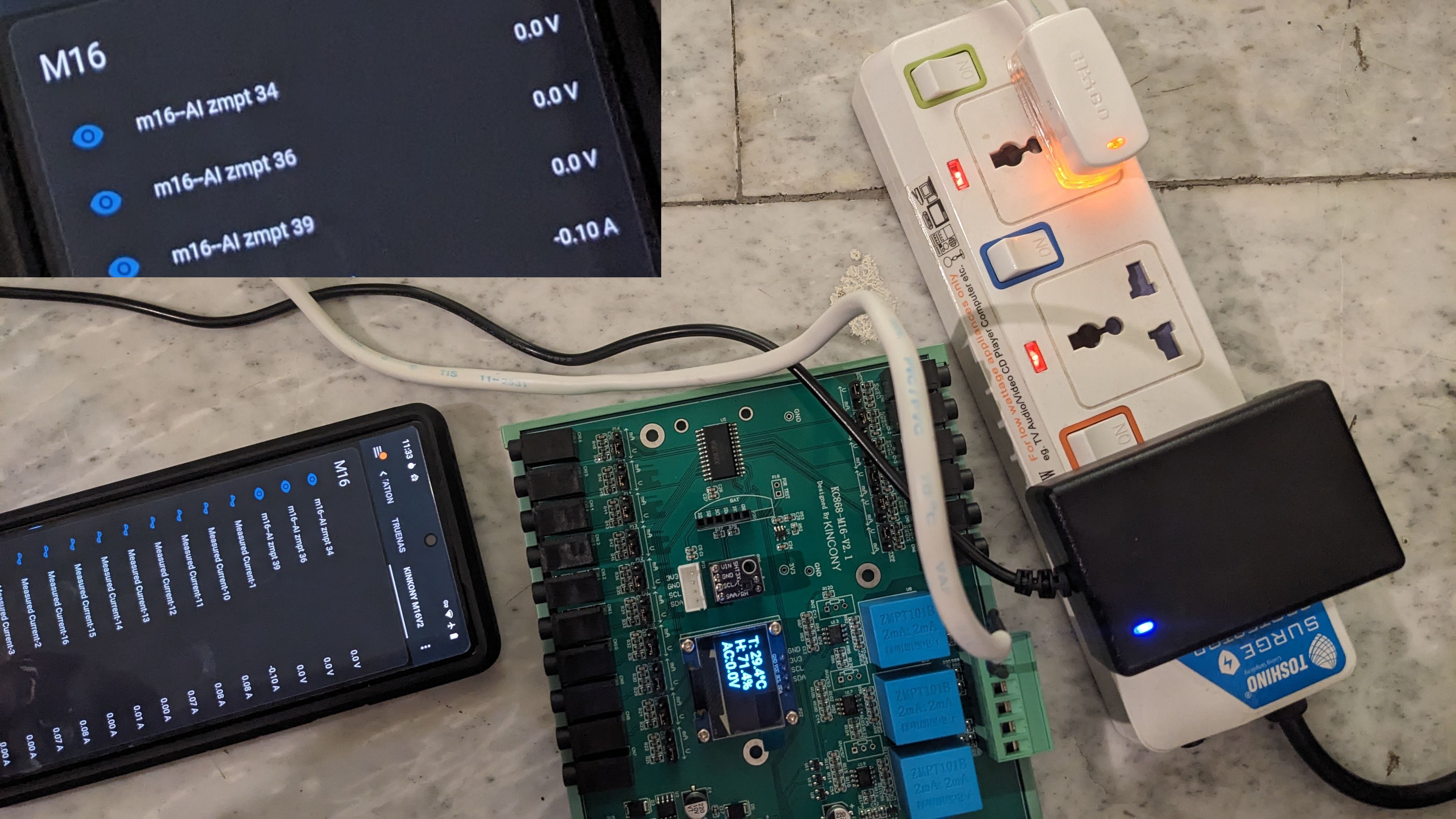
Attached in full image of the board.
(I'm aware that currently in the photo there is not 220v attached, the wires were in the way, so I removed the module for the photo)
I was playing around with the code today in zmpt101b and readAnalog on GPIO34, GPIO36, GPIO39 always seem to return 0.
ZMPT101B::getRmsVoltage Vnow: 0, rawRead: 0, zeroP: 0, PIN: 39
ZMPT101B::getRmsVoltage Vnow: 0, rawRead: 0, zeroP: 0, PIN: 36
ZMPT101B::getRmsVoltage Vnow: 0, rawRead: 0, zeroP: 0, PIN: 34
Is there any calibration required? Any suggestions on how to test the board or zmpt101b chip to see if this is the issue?

Posts: 6,193
Threads: 803
Joined: Oct 2020
Reputation:
151
how you connect with AC220v load wire for INPUT port. draw a photo.
Posts: 6
Threads: 1
Joined: Sep 2023
Reputation:
0
(09-14-2023, 10:32 PM)admin Wrote: how you connect with AC220v load wire for INPUT port. draw a photo.
I have some plugs connected to powerbar, which gets connected to input power from a standard socket in the house.
I've also tried with out the powerbar by connecting directly into socket.
See attached photo (or you can see in my original 1st photo)

Posts: 6,193
Threads: 803
Joined: Oct 2020
Reputation:
151
upload your M16v2 board esphome config yaml file at here.
Posts: 6
Threads: 1
Joined: Sep 2023
Reputation:
0
(09-15-2023, 06:32 AM)admin Wrote: upload your M16v2 board esphome config yaml file at here.
Default config provided in this forum. No changes except changing the Encryption key
Posts: 6
Threads: 1
Joined: Sep 2023
Reputation:
0
09-22-2023, 03:45 AM
(This post was last modified: 09-22-2023, 09:34 AM by sure.)
Watch these videos
Voltage Test 220v
https://streamable.com/9fmoah (video will expire in 2 days)
Battery 1.5v test on GPIO34
https://streamable.com/ive2gd (video will expire in 2 days)
I'm still not sure how to test to see what's wrong? Any suggestions? The GPIO pins on the ESP32 appear to work fine.
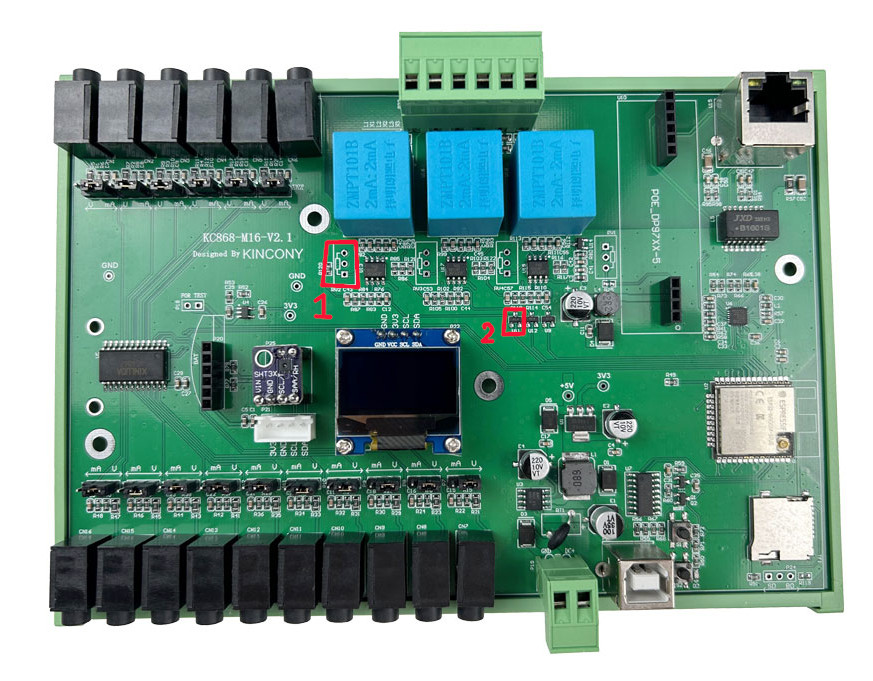
What are these for (image below)? And should I be getting voltage readings out of them (assuming things are working)
Should I return the device?

Posts: 6,193
Threads: 803
Joined: Oct 2020
Reputation:
151
09-22-2023, 08:13 AM
(This post was last modified: 09-22-2023, 08:18 AM by admin.)
because the default LCD is showed "voltage_2"
display:
- platform: ssd1306_i2c
model: "SSD1306 128x64"
address: 0x3C
lambda: |-
it.printf(0, 0, id(roboto), "T: %.1f°C", id(temperature).state);
it.printf(0, 20, id(roboto), "H: %.1f%%", id(humidity).state);
it.printf(0, 40, id(roboto), "AC:%.1fV", id(voltage_2).state);
you can replace : it.printf(0, 40, id(roboto), "AC:%.1fV", id(voltage_2).state); with
it.printf(0, 40, id(roboto), "AC:%.1fV", id(voltage_1).state); or
it.printf(0, 40, id(roboto), "AC:%.1fV", id(voltage_3).state);
voltage_1 voltage_2 voltage_3 means different voltage detect channel.
Posts: 6
Threads: 1
Joined: Sep 2023
Reputation:
0
09-22-2023, 09:11 AM
(This post was last modified: 09-22-2023, 09:35 AM by sure.)
(09-22-2023, 08:13 AM)admin Wrote: because the default LCD is showed "voltage_2"
display:
- platform: ssd1306_i2c
model: "SSD1306 128x64"
address: 0x3C
lambda: |-
it.printf(0, 0, id(roboto), "T: %.1f°C", id(temperature).state);
it.printf(0, 20, id(roboto), "H: %.1f%%", id(humidity).state);
it.printf(0, 40, id(roboto), "AC:%.1fV", id(voltage_2).state);
you can replace : it.printf(0, 40, id(roboto), "AC:%.1fV", id(voltage_2).state); with
it.printf(0, 40, id(roboto), "AC:%.1fV", id(voltage_1).state); or
it.printf(0, 40, id(roboto), "AC:%.1fV", id(voltage_3).state);
voltage_1 voltage_2 voltage_3 means different voltage detect channel.
No.
Your esphome.yaml in your post is set to voltage_2
Your esphome.yaml in your post's attachment is set to voltage_1.
I'm using your attachment code, and that's set to voltage_1 aka GPIO 34.
Here's your attachment code:
https://www.kincony.com/forum/attachment.php?aid=2666
Here's the diff between the two:
Code: --- m16-forum-post.yaml 2023-09-22 16:03:26.263079542 +0700
+++ m16-forum-attachment.yaml 2023-09-22 16:03:26.263079542 +0700
@@ -56,7 +56,7 @@
lambda: |-
it.printf(0, 0, id(roboto), "T: %.1f°C", id(temperature).state);
it.printf(0, 20, id(roboto), "H: %.1f%%", id(humidity).state);
- it.printf(0, 40, id(roboto), "AC:%.1fV", id(voltage_2).state);
+ it.printf(0, 40, id(roboto), "AC:%.1fV", id(voltage_1).state);
None of the voltages work as previously mentioned. They always have 0 volts. I noticed on your youtube video, that your volts in your video appear to float around 2.8v when nothing is connected to the board. Mine are always 0 volts. Another reason I suspect something is wrong.
So it really doesn't matter if it's voltage_1, 2 or 3. None of them work. None of them have ever worked since I've received the board.
Also in the video where I test with the 1.5V Battery test is on the 6th pin on the left side of the ESP32 aka GPIO34. That works fine. ADC reads voltage fine and displays via voltage_1.

Regardless, none of the voltages work. Not GPIO34, 36, 39. Not voltage_1, not voltage_2, not voltage_3.
Something is wrong. I asked for assistance with which rails I can test with a multi-meter to attempt to figure out where the problem is on the circuit. No response.
Here's your youtube video where you can see 2.8v when nothing is attached. On my board, these values are always 0v.

|


