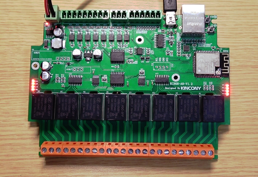
In the last article (https://www.kincony.com/kc868-a8-hardware-design-details.html) we got acquainted with the Kincony KC868-A8 controller and its circuitry, in this article we will analyze the programming of its functional blocks (inputs, relays, temperature sensors, Ethernet interface, etc.). You can use the code examples from this article in your projects on KC868-A8.
Personally, I like both Kincony KC868-A4 (https://www.kincony.com/kc868-a4-hardware-design-details.html) and KC868-A8, but our test subject today with its 8 digital inputs, 8 relays on board, I2C connector and Ethernet interface looks much more impressive and just asks for some kind of home automation project. Therefore, it was interesting for me to figure out what is there and how it works and how all this can be managed.
We will start the analysis of programming the KC868-A8 with the pinout of the ESP32 and finding out what and how is connected to it by Kincony engineers.
Pinout KC868-A8
To begin with, let’s get acquainted with the complete list of all functional blocks of the controller. In addition to the ESP32 (ESP-WROOM-32) module, the Kincony KC868-A8 board contains:
– 8 digital optoisolated inputs (“dry contact”)
– 2 analog inputs 0-5V
– 8 relays 10A 220V
– 4 contacts for connecting temperature and other sensors
– Connectors for connecting 433 MHz receiver/transmitter modules
– I2C connector
– Ethernet LAN8270A
Here, the “chip” of the KC868-A8 controller immediately stands out – the Ethernet network interface on a chip LAN8270A. The presence of this interface greatly expands the capabilities of the controller, but you have to pay for this by the “loss” of 9 GPIOs from their already extremely meager set.
The problem of lack of free pins of the ESP32 microcontroller, Kincony engineers solved by using port expanders, 8 digital inputs and 8 relays are connected to the ESP32 through PCF8574P port expanders with an I2C interface.
It is also need note the appearance on the board (compared to the KC868-A4) of an I2C connector for connecting additional equipment – this greatly expands the possibilities for adapting the controller to the tasks of your specific projects.
Below is the pinout of the KC868-A8 controller. The columns closest to the controller indicate the designations of lines and connections from the circuit diagram, and the columns farthest indicate the inputs and outputs of the functional blocks of the KC868-A8 controller.
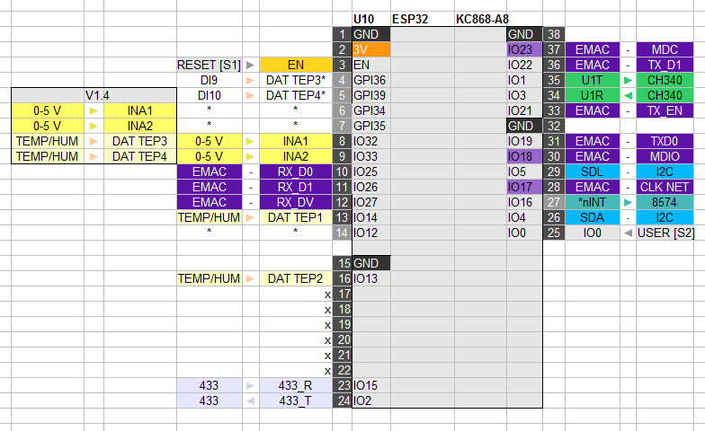
It needs to be clarified here: at the moment, the Kincony KC868-A8 controller has two versions – basic and upgraded V1.4. The pinout itself belongs to the basic version, and the changes made to version V1.4 are highlighted as a separate block. I have a version of the controller V1.4 at my disposal, so all further narration will refer to it.
A couple more explanations. The asterisks (*) in the diagram indicate connections that are “designed” by Kincony engineers, but are not actually on the board (at least in the basic version), and the cryptic designations “DI9” and “DI10” refer to “digital inputs” 9 and 10 (after 8 optocoupled digital inputs on the port expander) – all this is a creative (flaws or processing) of Kincony engineers.
Now, after understanding the pinout of the controller, you can begin to study the programming of the Kincony KC868-A8 functional blocks.
Software environment for KC868-A8
We will program the Kincony KC868-A8 controller in the Arduino 1.8.5 environment. I will not dwell here on installing ESP32 support in Arduino and other preparatory steps – there are a huge number of guides on this topic on the Internet.
To work with Kincony controller KC868-A8 we need to select the “NodeMCU-32S” option.
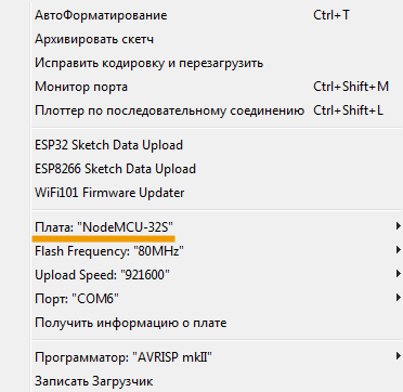
There is one more small but important point here: in the basic version of the NodeMCU-32S I2C board, the interface is tied to pins 21 and 22, and in our Kincony KC868-A8 controller these are pins 4 and 5. Accordingly, in the file
\hardware\espressif\esp32\variants\nodemcu-32s\pins_arduino.h
need to change the old definition
static const uint8_t SDA = 21;
static const uint8_t SCL = 22;
to match our KC868-A8
static const uint8_t SDA = 4;
static const uint8_t SCL = 5;
otherwise, neither the relay nor the digital inputs of the controller will work.
Now let’s move on to programming the function blocks of the KC868-A8.
Relay programming
Since a port expander on the PCF8574P chip is used to control the operation of the relay, the access to the relay in the code differs from the standard one. The expander works on the I2C interface
and to work with it you need to install a special library PCF8574_library (https://github.com/xreef/PCF8574_library).
The relay service chip PCF8574P has address 0x24 on the I2C bus and the object must be initialized accordingly to work with it. The relay control code itself is quite transparent:
/*
Kincony KC868-A8
Relays example
*/
#include “Arduino.h”
#include “PCF8574.h”
#define I2C_RELAYS_ADR 0x24
PCF8574 pcf(I2C_RELAYS_ADR);
void setup() {
Serial.begin(115200);
Serial.println(F(“Start Kincony KC868-A8 Relays example…”));
pcf.pinMode(P0, OUTPUT);
pcf.pinMode(P1, OUTPUT);
pcf.pinMode(P2, OUTPUT);
pcf.pinMode(P3, OUTPUT);
pcf.pinMode(P4, OUTPUT);
pcf.pinMode(P5, OUTPUT);
pcf.pinMode(P6, OUTPUT);
pcf.pinMode(P7, OUTPUT);
Serial.print(“Init PCF8574… “);
if (pcf.begin()){Serial.println(F(“Ok”));}
else {Serial.println(F(“Error”));}
}
void loop() {
pcf.digitalWrite(P0, HIGH);
Serial.print(F(“Relay #”)); Serial.print(P0); Serial.println(F(” ON”));
delay(10000);
pcf.digitalWrite(P0, LOW);
Serial.print(F(“Relay #”)); Serial.print(P0); Serial.println(F(” OFF”));
delay(10000);
}
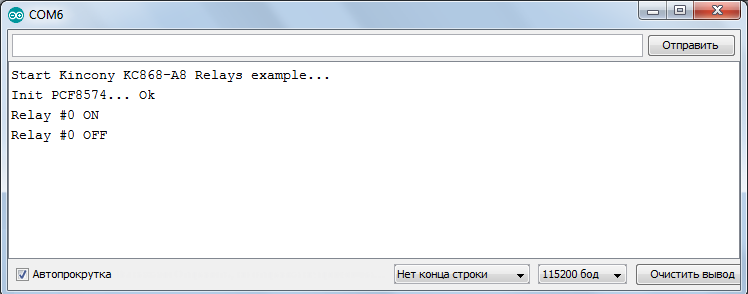
And it will not be difficult for you to implement any relay control logic of the Kincony KC868-A8 controller based on it. The result of the output to Serial of the test sketch of relay control through the PCF8574P port expander:
Digital inputs
The Kincony KC868-A8 controller has 8 optocoupled dry contact digital inputs, which are connected via the I2C port expander PCF8574P. As with relays, the digital inputs are programmed using the PCF8574_library.
The PCF8574P digital input service chip has address 0x22 on the I2C bus. The code, as in the case of the relay, is also simple and transparent and should not cause you any difficulties:
/*
Kincony KC868-A8
Digital input example
*/
#include “Arduino.h”
#include “PCF8574.h”
#define I2C_DIGITAL_ADR 0x22
PCF8574 pcf(I2C_DIGITAL_ADR);
void setup() {
Serial.begin(115200);
Serial.println(F(“Start Kincony KC868-A8 Digital input example…”));
pcf.pinMode(P0, INPUT);
pcf.pinMode(P1, INPUT);
pcf.pinMode(P2, INPUT);
pcf.pinMode(P3, INPUT);
pcf.pinMode(P4, INPUT);
pcf.pinMode(P5, INPUT);
pcf.pinMode(P6, INPUT);
pcf.pinMode(P7, INPUT);
Serial.print(“Init PCF8574… “);
if (pcf.begin()){Serial.println(F(“Ok”));}
else {Serial.println(F(“Error”));}
delay(20);
}
void loop() {
byte val1 = pcf.digitalRead(P0);
byte val2 = pcf.digitalRead(P1);
byte val3 = pcf.digitalRead(P2);
byte val4 = pcf.digitalRead(P3);
byte val5 = pcf.digitalRead(P4);
byte val6 = pcf.digitalRead(P5);
byte val7 = pcf.digitalRead(P6);
byte val8 = pcf.digitalRead(P7);
if (val1 == LOW) Serial.println(“Key1 pressed”);
if (val2 == LOW) Serial.println(“Key2 pressed”);
if (val3 == LOW) Serial.println(“Key3 pressed”);
if (val4 == LOW) Serial.println(“Key4 pressed”);
if (val5 == LOW) Serial.println(“Key5 pressed”);
if (val6 == LOW) Serial.println(“Key6 pressed”);
if (val7 == LOW) Serial.println(“Key7 pressed”);
if (val8 == LOW) Serial.println(“Key8 pressed”);
delay(300);
}
The result of the test sketch for working with digital inputs through an I2C port expander PCF8574P:
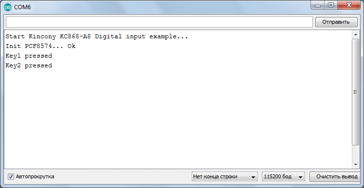
Everything works clearly and predictably, as it should work.
Analog inputs
Kincony KC868-A8 has 2 analog inputs for 0-5 V signals. The KC868-A8 has some confusion with these inputs – they are wired differently in different versions of the board. We will arrange the analog inputs on the device for version V1.4 in which they are connected to GPIO34 and GPIO35 (in the basic version, these are GPIO32 and GPIO33).
The code is also extremely simple and boils down to calling the standard analogRead() function and then analyzing the returned values.
/*
Kincony KC868-A8
Analog example
*/
#include “Arduino.h”
#define ANALOG_A1 34 // IO34 (V1.4)
#define ANALOG_A2 35 // IO35 (V1.4)
void setup() {
Serial.begin(115200);
Serial.println(F(“Start Kincony KC868-A8 Analog example…”));
pinMode(ANALOG_A1, INPUT);
pinMode(ANALOG_A2, INPUT);
}
void loop() {
Serial.printf(“Current Reading A1 on Pin%d=%d\n”, ANALOG_A1, analogRead(ANALOG_A1));
Serial.printf(“Current Reading A2 on Pin%d=%d\n”, ANALOG_A2, analogRead(ANALOG_A2));
delay(5000);
}
Temperature and Humidity Sensors
The KC868-A8 also has some confusion with sensor inputs – they are also wired differently in different versions of the board. In version V1.4, these are pins 14, 13, 32, 33. These GPIOs can be connected to temperature sensors, humidity sensors, or any other sensors that are suitable for the type of connection. You just need to remember that the data lines are already pulled up to the supply voltage on the board.
To work with DS18B20 temperature sensors, the DS18B20 (https://github.com/matmunk/DS18B20) and OneWire (https://github.com/PaulStoffregen/OneWire) libraries are required. Below is the code for one DS18B20 sensor connected to the KC868-A8 board on GPIO14.
/*
Kincony KC868-A8
DS18B20 example
*/
#include <DS18B20.h>
#define LOW_ALARM 30
#define HIGH_ALARM 40
DS18B20 ds(14); // 14, 13, 32, 33 (V1.4)
void setup() {
Serial.begin(115200);
Serial.println(F(“Start Kincony KC868-A8 DS18B20 example…”));
ds.doConversion();
while (ds.selectNext()) {
ds.setAlarms(LOW_ALARM, HIGH_ALARM);
}
}
void loop() {
ds.doConversion();
while (ds.selectNextAlarm()) {
Serial.print(“Alarm Low: “); Serial.print(ds.getAlarmLow()); Serial.println(” °C”);
Serial.print(“Alarm High: “); Serial.print(ds.getAlarmHigh()); Serial.println(” °C”);
Serial.print(“Temperature: “); Serial.print(ds.getTempC()); Serial.println(” °C\n”);
}
delay(2000);
}
Activation thresholds are set in the code, and if the controlled temperature goes beyond certain values, a corresponding message is displayed in Serial.
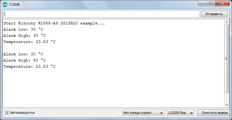
The DS18B20 library contains various examples of using the DS18B20 temperature sensors
– you can choose the most suitable for your project.
Receiver/transmitter 433 MHz
Here we will not dwell on the use of the receiver and transmitter on the 433MHz, you can read about it in the article (https://www.kincony.com/how-to-code-by-arduino-ide.htmlhttps://www.kincony.com/how-to-code-by-arduino-ide.html) about the board KC868-A4.
I will only mention that in KC868-A8 the receiver and transmitter are connected to GPIO15 and GPIO2.
And in the event that you do not need work with wireless data transmission at 433 MHz, you can use GPIO15 and GPIO2 to connect some of your components (see the KC868-A8 circuitry from the previous article).
Ethernet LAN8270A
The Kincony KC868-A8 controller has a LAN8270A Ethernet interface chip on board and the ability to connect and work via a wired Ethernet network. At the same time, ESP32 makes it possible to work via a wireless Wi-Fi interface. That is, we have the opportunity to connect our controller either via wired Ethernet, or via wireless Wi-Fi, or both via both interfaces at the same time. This allows for very flexible control of the controller in various situations (for example, in the event of loss of communication over a wireless channel, etc.).
Using the Ethernet interface with the ESP32 is quite simple. First you need to specify the appropriate libraries:
#include <ETH.h>
#include <SPI.h>
Then the type of chip used:
#define ETH_TYPE ETH_PHY_LAN8720
Control pins:
#define ETH_CLK_MODE ETH_CLOCK_GPIO17_OUT
#define ETH_MDC_PIN 23
#define ETH_MDIO_PIN 18
And other interface settings:
#define ETH_POWER_PIN -1
#define ETH_ADDR 0
#define NRST 5
Next comes the test sketch code, which initializes the Ethernet interface and makes requests to the site on the Internet.
/*
Kincony KC868-A8
Ethernet example
*/
#include <ETH.h>
#include <SPI.h>
#define ETH_CLK_MODE ETH_CLOCK_GPIO17_OUT
#define ETH_POWER_PIN -1
#define ETH_TYPE ETH_PHY_LAN8720
#define ETH_ADDR 0
#define ETH_MDC_PIN 23
#define ETH_MDIO_PIN 18
#define NRST 5
static bool eth_connected = false;
void WiFiEvent(WiFiEvent_t event) {
switch (event) {
case SYSTEM_EVENT_ETH_START:
Serial.println(“ETH Started”);
ETH.setHostname(“esp32-ethernet”);
break;
case SYSTEM_EVENT_ETH_CONNECTED:
Serial.println(“ETH Connected”);
break;
case SYSTEM_EVENT_ETH_GOT_IP:
Serial.print(“ETH MAC: “); Serial.print(ETH.macAddress());
Serial.print(“, IPv4: “); Serial.print(ETH.localIP());
if (ETH.fullDuplex()) {Serial.print(“, FULL_DUPLEX”);}
Serial.print(“, “); Serial.print(ETH.linkSpeed()); Serial.println(“Mbps”);
eth_connected = true;
break;
case SYSTEM_EVENT_ETH_DISCONNECTED:
Serial.println(“ETH Disconnected”);
eth_connected = false;
break;
case SYSTEM_EVENT_ETH_STOP:
Serial.println(“ETH Stopped”);
eth_connected = false;
break;
default:
break;
}
} // WiFiEvent( )
void testClient(const char *host, uint16_t port) {
Serial.print(“\nconnecting to “); Serial.println(host);
WiFiClient client;
if (!client.connect(host, port)) {
Serial.println(“connection failed”);
return;
}
client.printf(“GET / HTTP/1.1\r\nHost: %s\r\n\r\n”, host);
while (client.connected() && !client.available());
while (client.available()) {
Serial.write(client.read());
}
Serial.println(“closing connection\n”);
client.stop();
}
void setup() {
Serial.begin(115200);
Serial.println(F(“Start Kincony KC868-A8 Ethernet example…”));
WiFi.onEvent(WiFiEvent);
pinMode(NRST, OUTPUT);
digitalWrite(NRST, 0); delay(200);
digitalWrite(NRST, 1); delay(200);
digitalWrite(NRST, 0); delay(200);
digitalWrite(NRST, 1);
ETH.begin(ETH_ADDR, ETH_POWER_PIN, ETH_MDC_PIN, ETH_MDIO_PIN, ETH_TYPE,
ETH_CLK_MODE);
}
void loop() {
if (eth_connected) {
testClient(“baidu.com”, 80);
}
delay(10000);
}
Here: network event monitoring is initialized.
WiFi.onEvent(WiFiEvent);
The LAN8270A chip is being launched (which is unnecessary in our case, since the NRST pin on the KC868-A8 not connected to the ESP32 at all).
pinMode(NRST, OUTPUT);
digitalWrite(NRST, 0); delay(200);
digitalWrite(NRST, 1); delay(200);
digitalWrite(NRST, 0); delay(200);
digitalWrite(NRST, 1);
And the Ethernet interface is launched with the appropriate parameters:
ETH.begin(ETH_ADDR, ETH_POWER_PIN, ETH_MDC_PIN, ETH_MDIO_PIN, ETH_TYPE,
ETH_CLK_MODE);
Further in the cycle, requests are sent to the site on the Internet:
void loop() {
if (eth_connected) {
testClient(“baidu.com”, 80);
}
delay(10000);
}
And the job of sending requests is performed by the testClient() function.
void testClient(const char *host, uint16_t port) {
Serial.print(“\nconnecting to “); Serial.println(host);
WiFiClient client;
if (!client.connect(host, port)) {
Serial.println(“connection failed”);
return;
}
client.printf(“GET / HTTP/1.1\r\nHost: %s\r\n\r\n”, host);
while (client.connected() && !client.available());
while (client.available()) {
Serial.write(client.read());
}
Serial.println(“closing connection\n”);
client.stop();
}
Program structure
void WiFiEvent(WiFiEvent_t event) {
switch (event) {
case SYSTEM_EVENT_ETH_START:
Serial.println(“ETH Started”);
ETH.setHostname(“esp32-ethernet”);
break;
case SYSTEM_EVENT_ETH_CONNECTED:
Serial.println(“ETH Connected”);
break;
case SYSTEM_EVENT_ETH_GOT_IP:
Serial.print(“ETH MAC: “); Serial.print(ETH.macAddress());
Serial.print(“, IPv4: “); Serial.print(ETH.localIP());
if (ETH.fullDuplex()) {Serial.print(“, FULL_DUPLEX”);}
Serial.print(“, “); Serial.print(ETH.linkSpeed()); Serial.println(“Mbps”);
eth_connected = true;
break;
case SYSTEM_EVENT_ETH_DISCONNECTED:
Serial.println(“ETH Disconnected”);
eth_connected = false;
break;
case SYSTEM_EVENT_ETH_STOP:
Serial.println(“ETH Stopped”);
eth_connected = false;
break;
default:
break;
}
} // WiFiEvent( )
responsible for the analysis, interpretation and visualization of Ethernet network events.
The result of the test sketch of the Kincony KC868-A8 controller via the Ethernet interface:
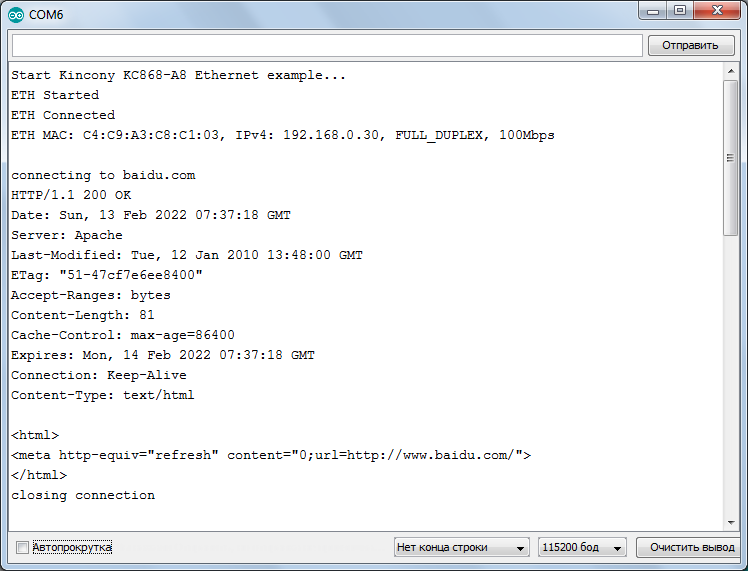
Everything works clearly and predictably: during the testing process, no problems were noticed with the network operation of the ESP32 and LAN8270A bundle.
Conclusion
In this article, we looked at examples of programming various functional blocks of the Kincony KC868-A8 controller. We will devote the next article to the analysis of more complex examples of working with the KC868-A8 and analyze in detail the problems of working on two interfaces – wired Ethernet and wireless Wi-Fi.


