Note: This document use for KinCony KCS v3 firmware smart controller.
1. Download “KCS” firmware to KinCony ESP32-S3 series board.
a. Download “ESP32 download tool” from https://www.kincony.com/wp-content/uploads/2022/08/flash_download_tool_3.9.2.zip and firmware BIN file from KinCony forum.
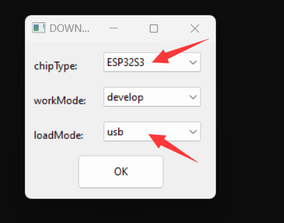
b. Open “flash_download_tool_3.9.2.exe”, (firstly MUST connect USB cable to your board, power on)
chose “ESP32-S3” and workMode=“develop” loadMode: “usb” item.
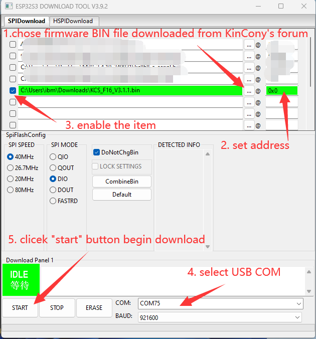
c. Chose KCS v3 firmware BIN file and COM port then begin download. Total 5 steps.
2. Use ethernet cable or WiFi config setting.
a. use ethernet cable connect board to your router, make sure your computer also connect with same router, just all in one local network.
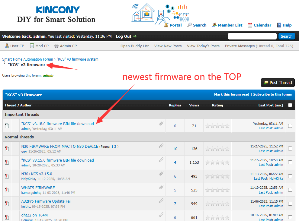
b. Power on of your board, you can use KinCony scan device tool to find output board IP address.
https://www.kincony.com/download/KinCony-SCAN_Device.zip
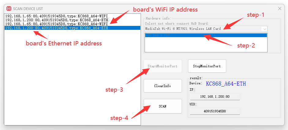
Total 5 steps to find out IP address.
Step-1: chose your computer network adapter when you are using.
Step-2: chose your computer IP address item.
Step-3: click “StartMonitorPort” button.
Step-4: click “SCAN” button.
Step-5: board’s ethernet or WiFi IP address , ID and type name will be listed.
c. another easy way, you can check IP address on LCD display. Here showed wifi and ethernet IP address.
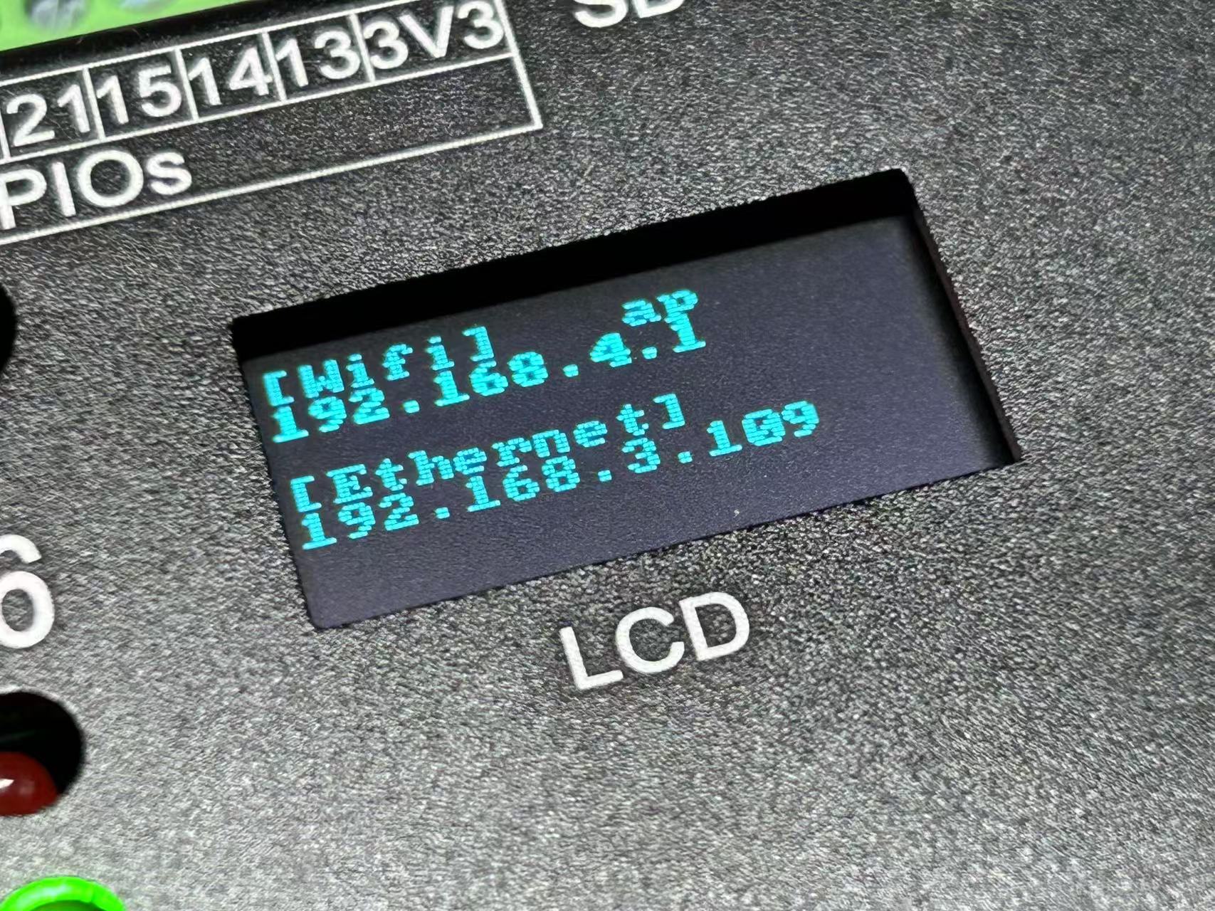
If you first time power on , you board will be found by ethernet IP address. Because your WiFi is work as “AP” mode as default. After you config your WiFi as “STA” mode, you will find out the WiFi IP address by KinCony scan device tool.
You can use ethernet IP address login by web browser to config board setting.
Note: if you want config only by WiFi, when power on, your computer will find the “AP” hotspot, WiFi signal named “board name” + “ID”.
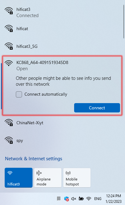
Let your computer connect to the “AP”, it’s without password, after you connected, just use http://192.168.4.1 to login by webpage.
If you can’t see the “AP”, you can “hold on” board’s function button (ESP32 GPIO0) >10 seconds, then board will be set to factory, default state is “AP”.
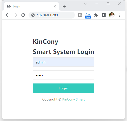
You can login webpage by ethernet IP or WiFi IP. Here is sample login by ethernet IP address 192.168.1.200
Login user name and password default are “admin” “admin”
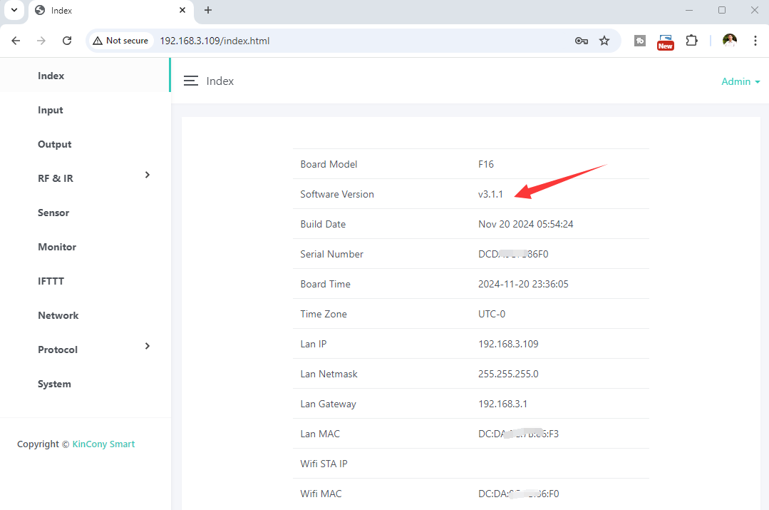
You can see this home page. Some parameters are shown.
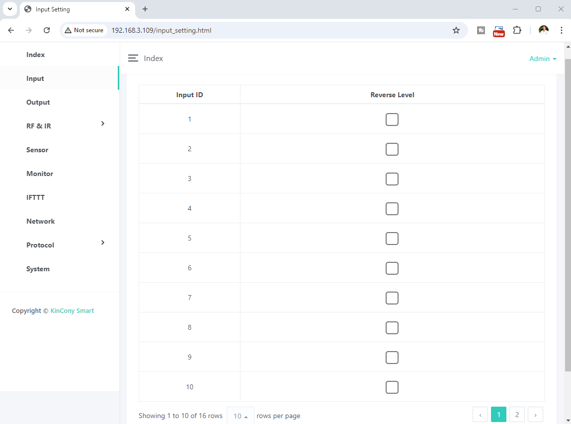
Here is INPUT webpage. Set every digital input port how to work with OUTPUT ports.
“Reverse Level”: if checked, the effective level at the digital input port becomes inverted. Just digital input use by “HIGH” or “LOW” level. Usually digital input port short with GND = trigger.

Here is OUTPUT webpage.

“hold on”: keep the state after turn ON/OFF
“delay”: after you turn ON digital output, will auto turn OFF after a “delay time” you have preset.
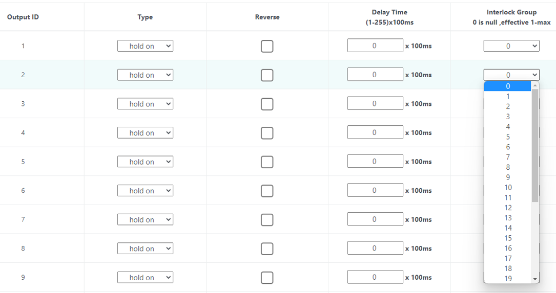
“Interlock group”: set interlock group for digital output. If set to “0” , disable interlock function. If “Output1” set to “1” and “Output2” set to “1” = Output1 and Output2 work with interlock. If “Output3” set to “2” and “Output4” set to “2” = Output3 and Output4 work with interlock. For example , KC868-A64 have 64 channel digital output, so total will have 64/2=32 interlock groups.
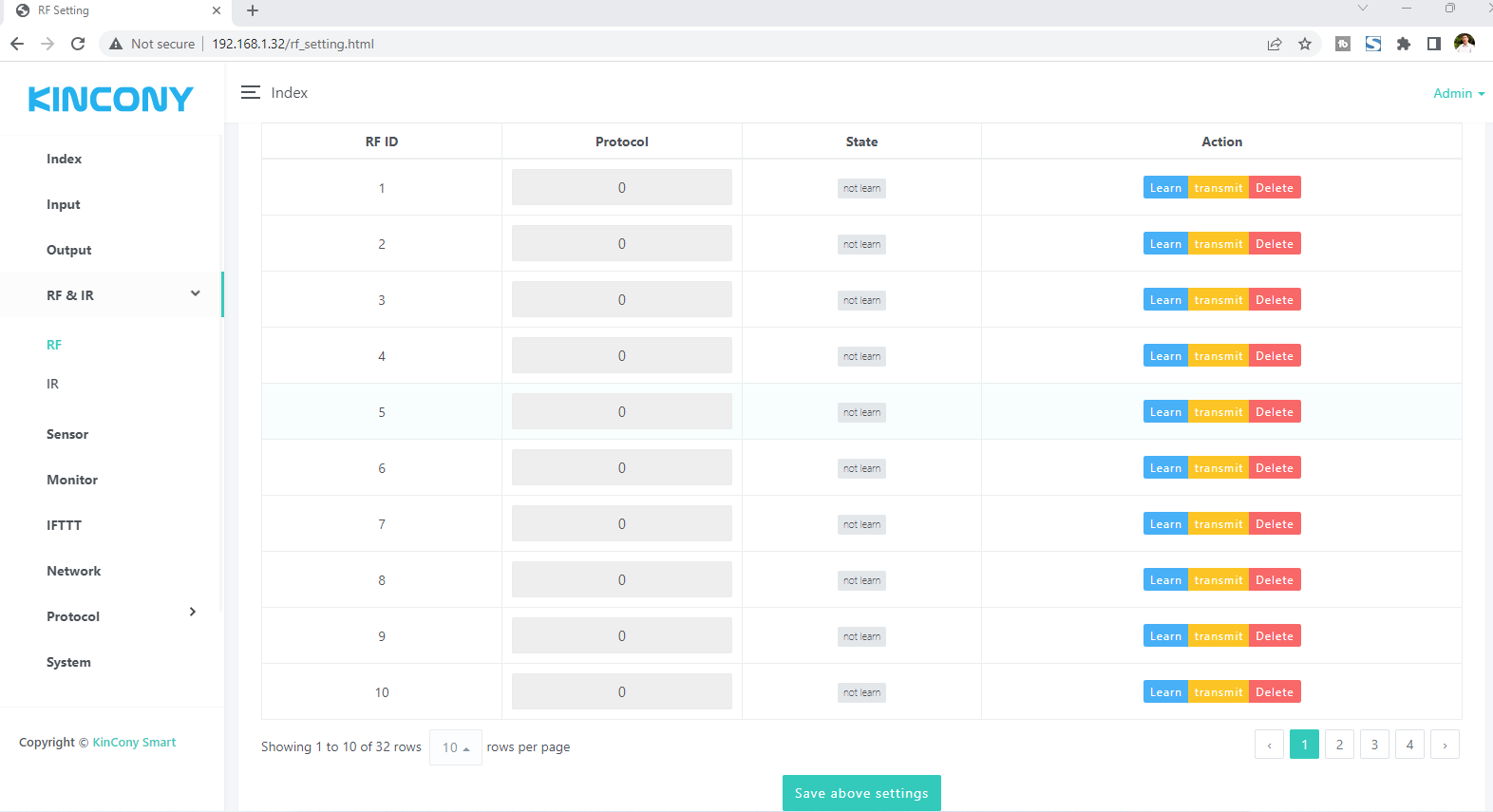
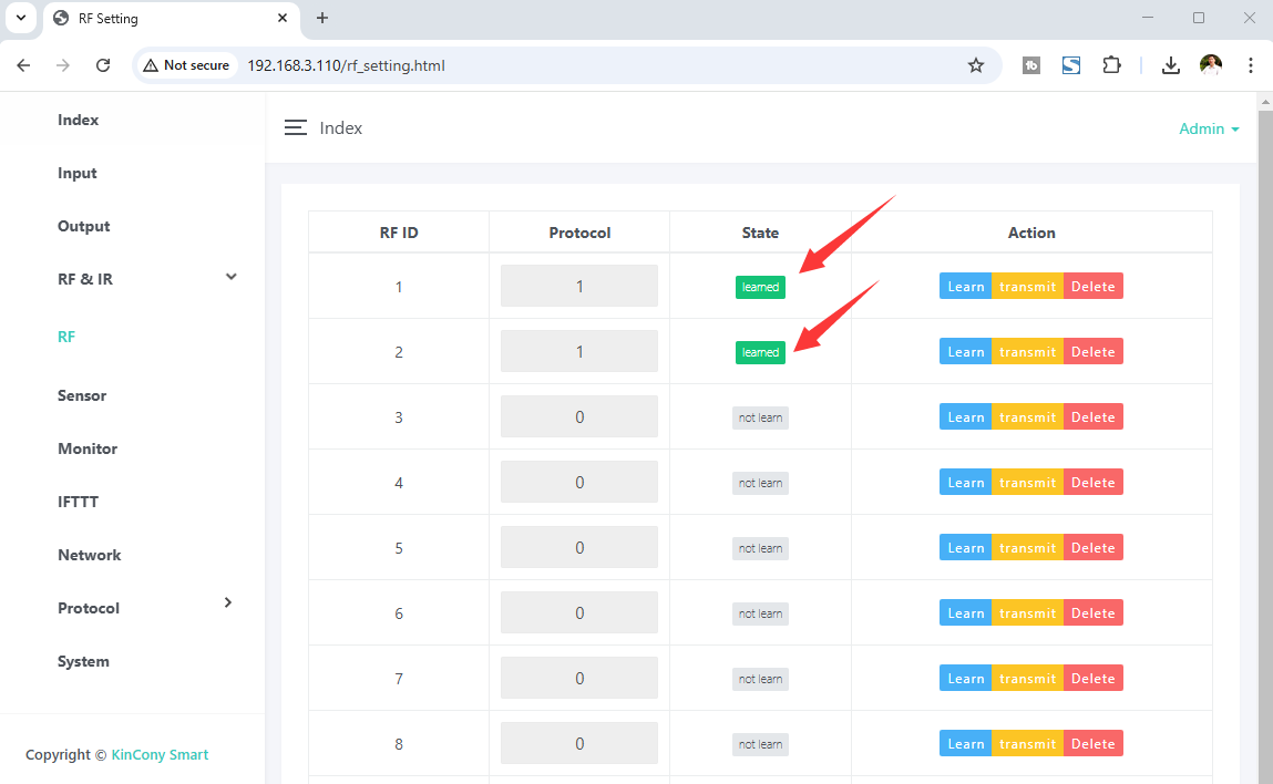
Here is RF webpage. It support “Learn” , “transmit”, “Delete” RF code. Support EV1527 or PT2262, PT2264 wireless remote code.
When press “Learn” blue button, begin study mode, wait for you press remote’s button, it will show message:
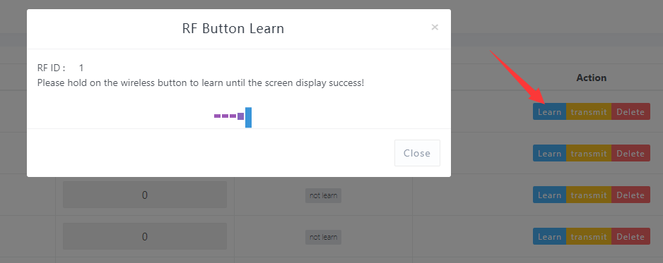
Then press one button of remote:

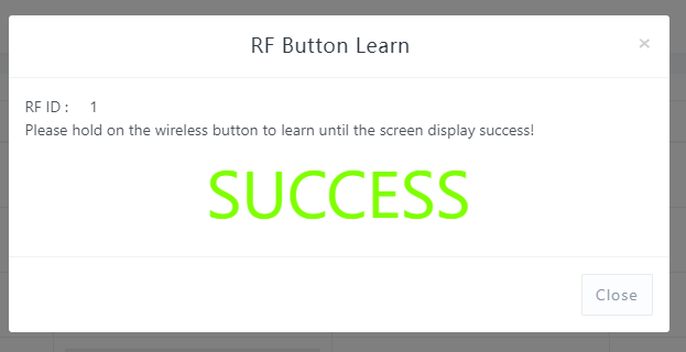
If learn signal successful, will show:
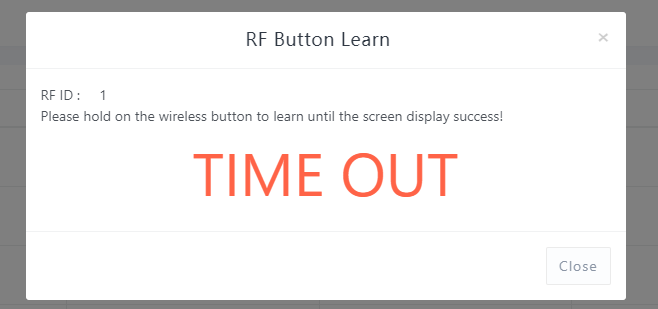
If learn signal failure or time out , will show:
After you learned signal, then it will be saved on controller.
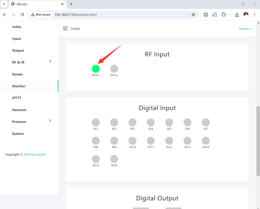
you can monitor your RF sensor state on “monitor” webpage. if received RF signal, ico will turn GREEN.
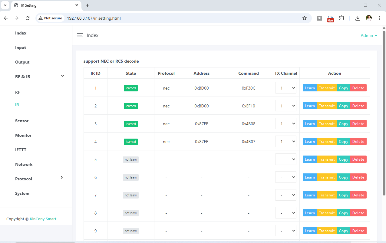
Here is IR webpage. It support “Learn” , “transmit”, “Delete” IR code. Such as TV, DVD, air conditioner, fans or other IR devices.
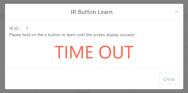
When press “Learn” blue button, begin study mode, wait for you press IR remote’s button, it will show message:
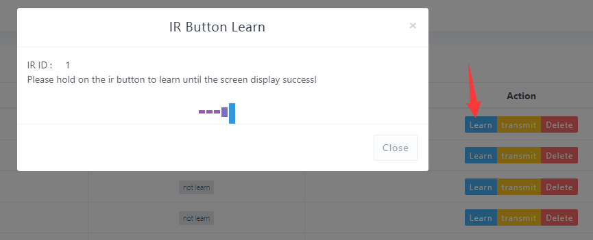
Then press one button of remote send IR signal to IR recevier on board:

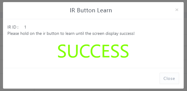
If learn signal successful, will show:
If learn signal failure or time out , will show:
After you learned signal, then it will be saved on controller.
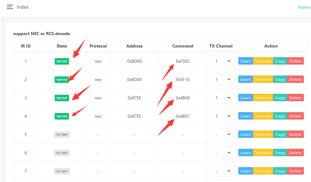
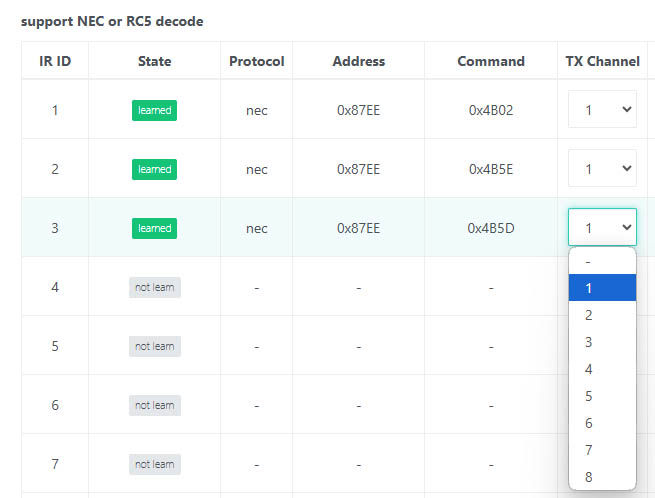
TX channel means IR tube ID, because some of IR controller have multi IR send tube, such as AG8 IR Controller.
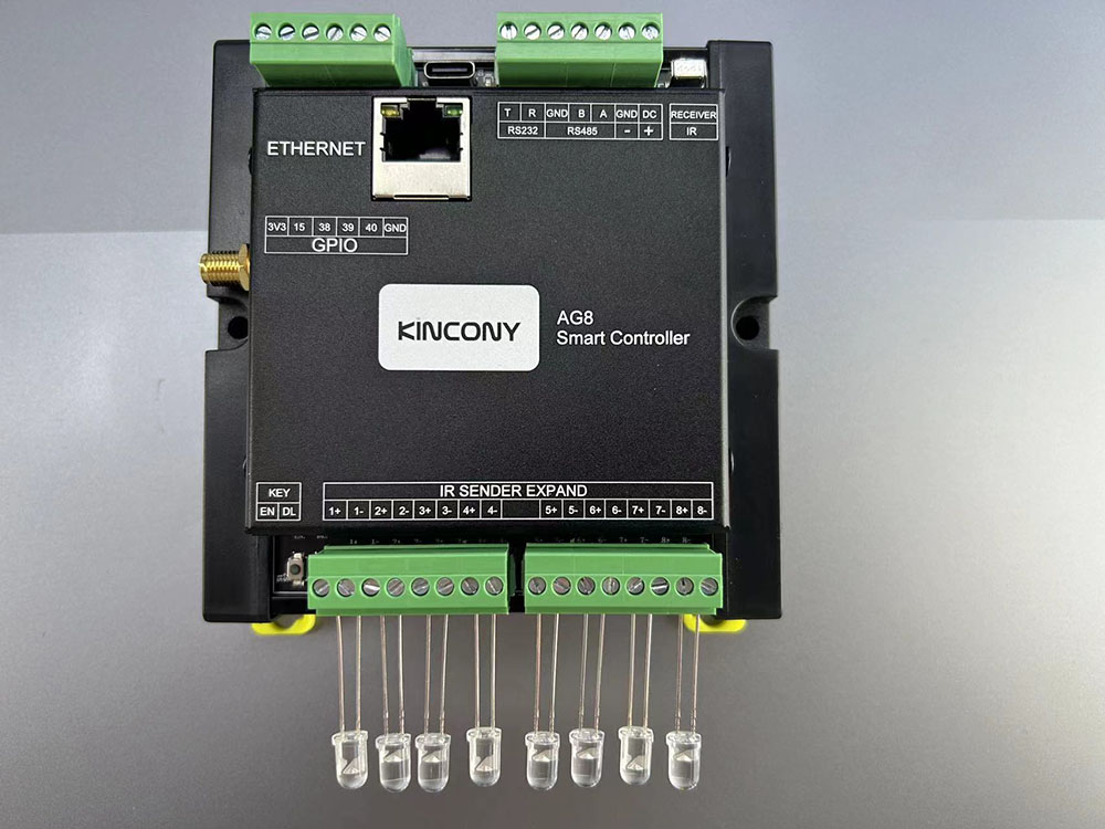
TX channel set which IR tube to send siganl.
note: if you using NEC or RC5 IR code remote, after decoded, you can use IR remote button as a binary sensor, use by KCS webpage or home assistant. if your remote can’t be decode IR signal, just can’t use for binary sensor, but also can send out the learned IR signal.
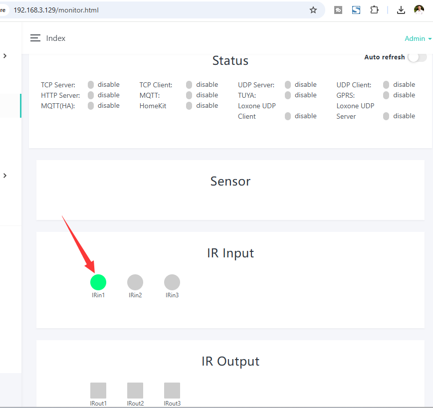
when received IR signal, input item will show GREEN. you can click “IR Output” button to send IR signal manaully.
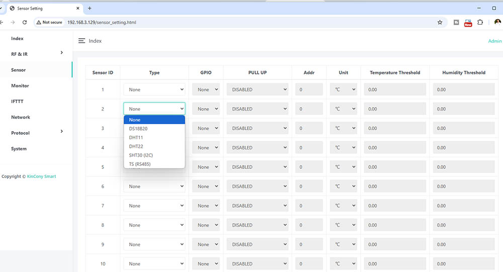
Here is sensor webpage. You can set different sensor model for:
1-wire GPIO ports for DS18B20 / DHT11 / DHT22 sensor.
I2C bus port use SHT30 sensor.
RS485 for KinCony TS temperature and humidity sensor.
“PULL UP” is option for GPIO enable / disable pull up resistance by software. if without this option, that means already include pull up resistance on PCB.
Temperature Threshold:
If the preset difference is exceeded, temperature data will be auto updated.
For example: “Temperature Threshold” =2 now temperature is 28°C, so next time , when new temperature is >30°C(28+2) or <26°C(28-2) will update.
Humidity Threshold:
If the preset difference is exceeded, humidity data will be auto updated.
For example: “Humidity Threshold” =10 now humidity is 75%, so next time , when new humidity is >85%(75+10) or <65%(75-10) will update.

Here is monitor webpage.
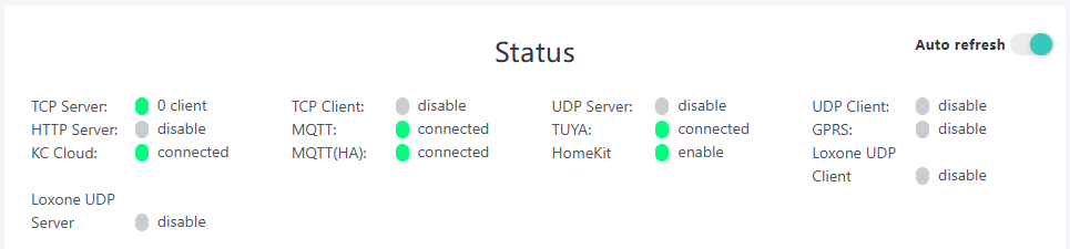
Monitor all protocol work state, whether have connect to server or have a client have connected.
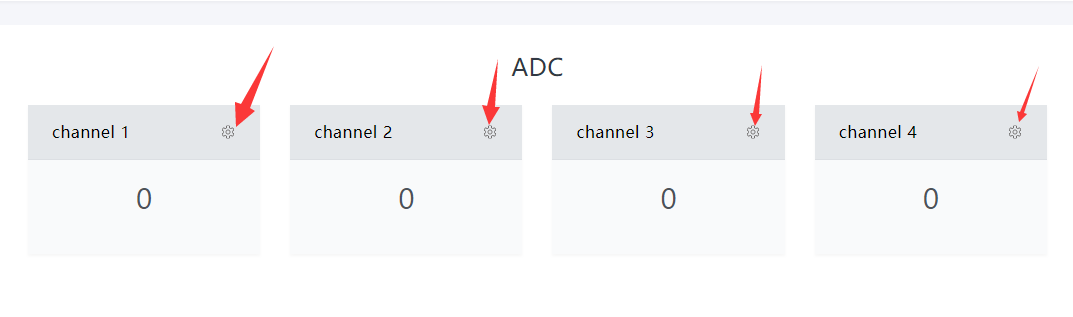
Monitor ADC value.
In order to easily view the values of each sensor, we can set a separate sensor channel name, range, display unit, and automatically reported threshold for each sensor.
Just click “gear” image, will show the config page.
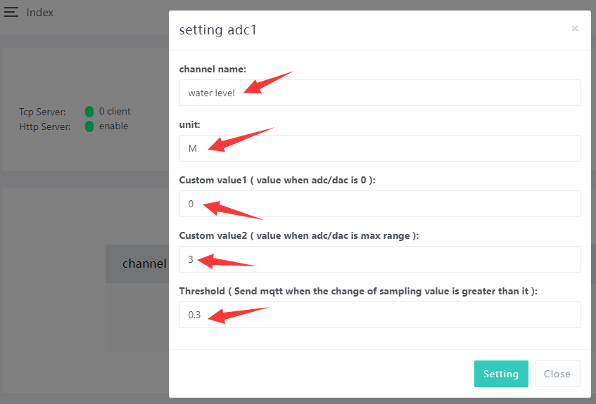
Fox example, we set a water level analog sensor, name is “water level”, unit is M (meter), Custom value1 and value2 means: if you are using DC 0-5v analog sensor, when sensor voltage is 0v, what’s “Custom value1” corresponding value. when sensor voltage is 5v, what’s “Custom value2” corresponding value.
So sensor dc 0-5v — convert à 0-3 meter
If you are using sensor 4-20mA, so 4-20mA 4mA=Custom value1, 20mA is Custom value2.
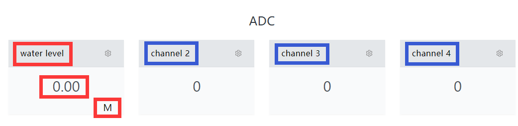
Then you will see the actually sensor name , value and unit on the monitor webpage.
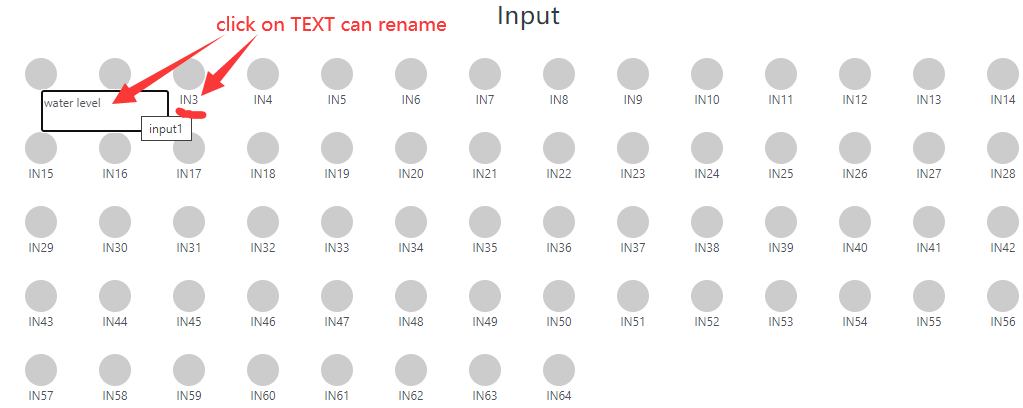
Double click on the input name’s TEXT can be rename by yourself.
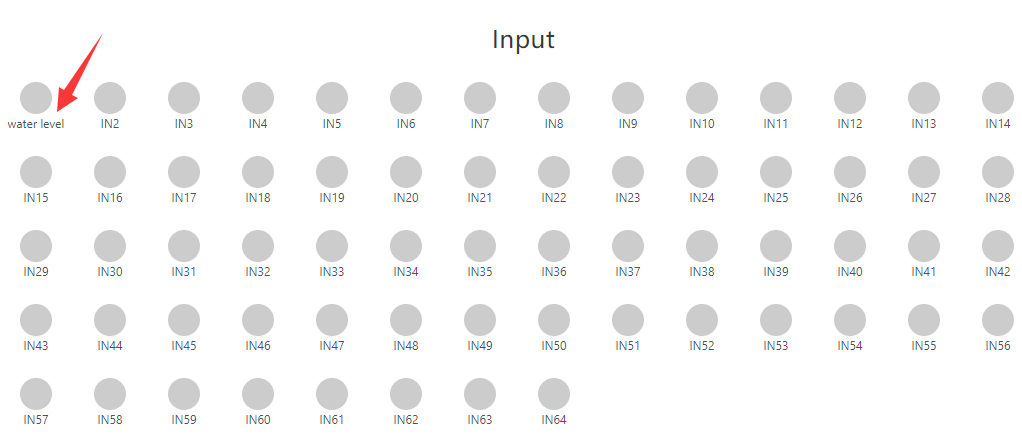
After renamed.
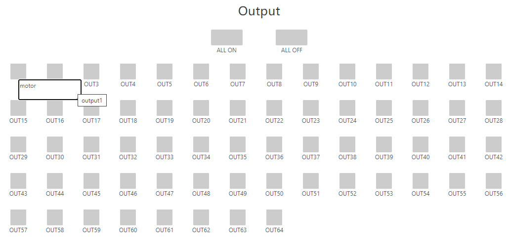
Use the same way (double click TEXT) can rename of the output ports.
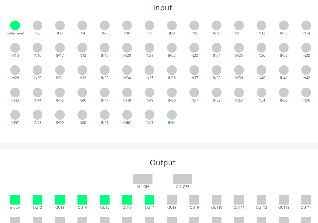
Green ico for INPUT means triggered.
Green ico for OUTPUT means output is ON state.
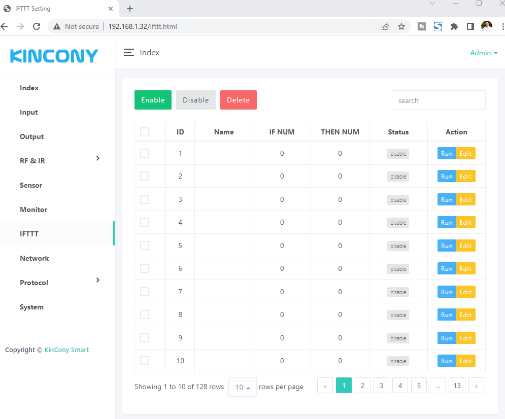
Here is IFTTT webpage. It can create IFTTT AUTOMATION. Press “Run” blue button for running testing. Press “Edit” yellow button for modify.
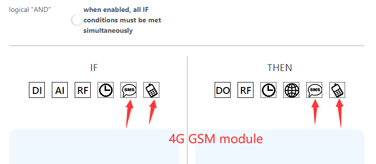
If your board support 4G SIM7600 module, there will have “SMS” and “voice call” ICO.
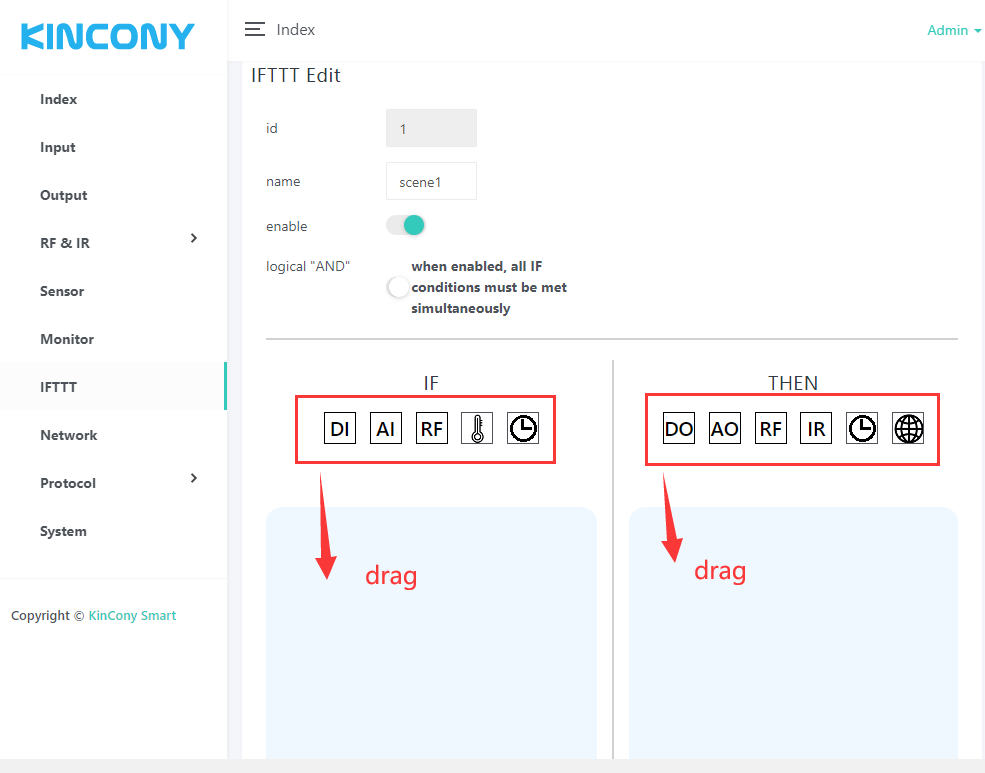
You can rename the AUTOMATION name. “enable” or “disable” it.
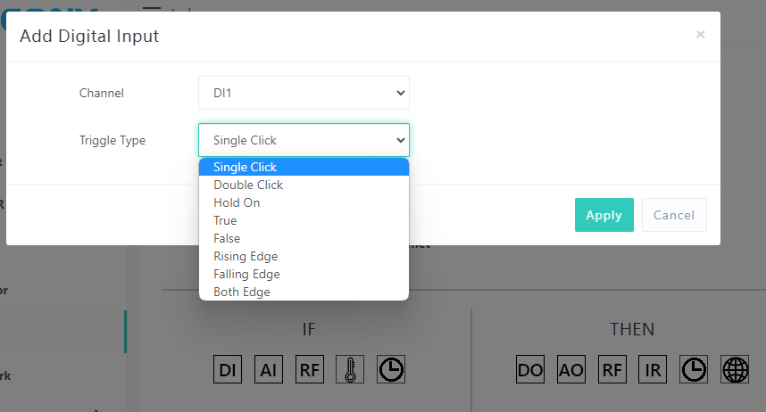
DI options:
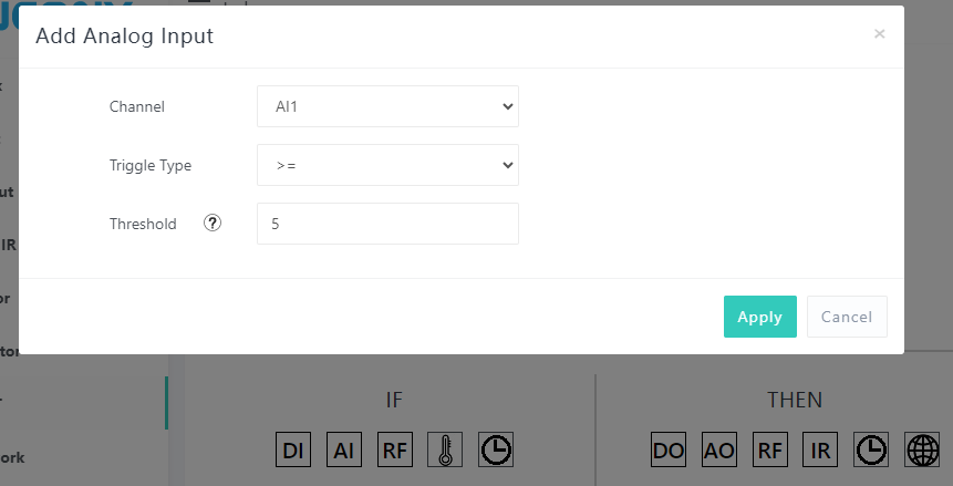
AI options:
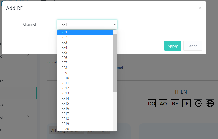
RF options:
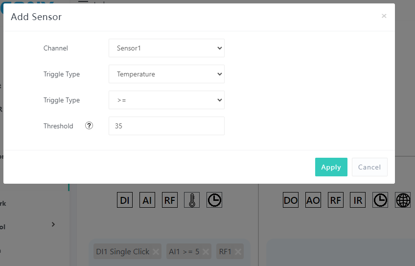
Sensor options:
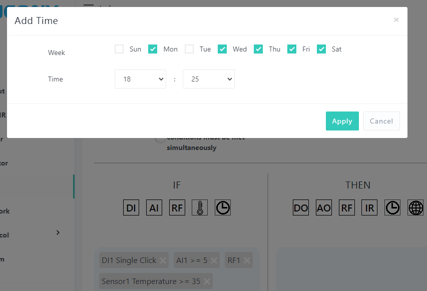
Timer options:
If your board support 4G SIM7600 module, there will have “SMS” and “voice call” options:
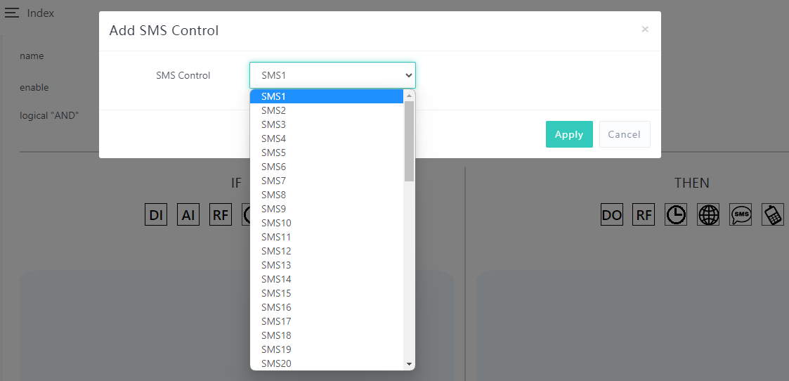
SMS options:
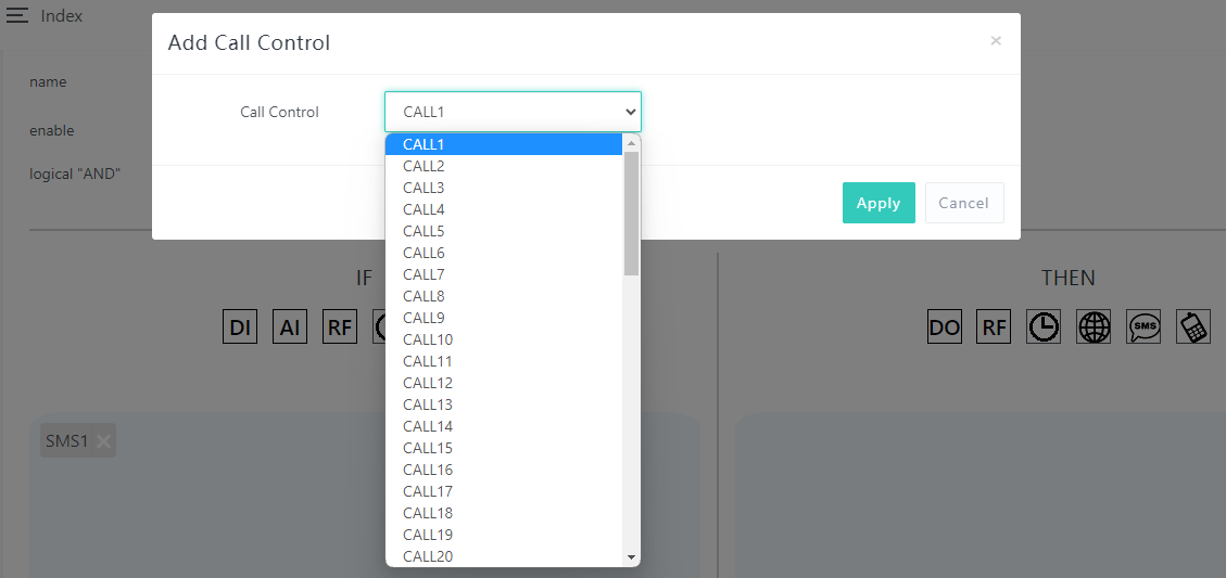
Voice call options:
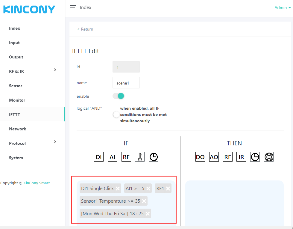
If enable [logical “AND”] option, All IF conditions need to be met before the action can be executed. If “disable” just All IF conditions is “OR” logical.
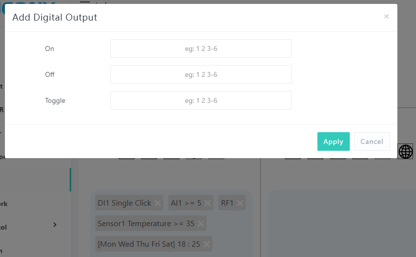
DO options:
you can set and separated by a “space”. You can enter “1 2 3 4 5” or “1-5” in the corresponding option to do something of digital output No.1-5
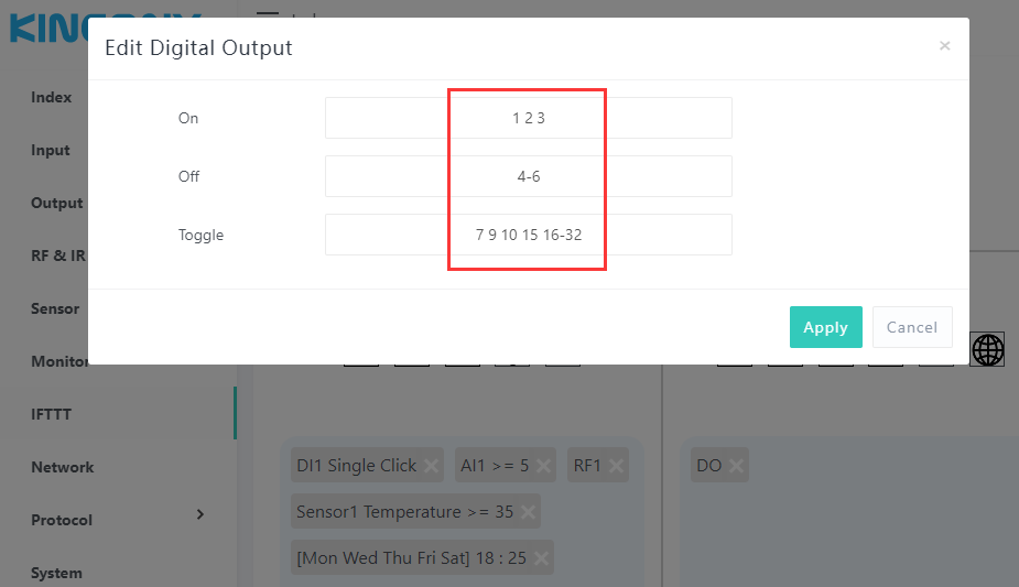
Fox example:
The config photo that means:
Turn ON digital output 1,2,3,
Turn OFF digital output 4,5,6
Toggle digital output 7,9,10,15,16,17,18,19,20,21,22,23,24,25,26,27,28,29,30,31,32
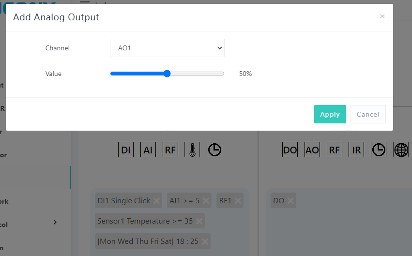
AO options:
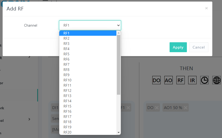
RF options:
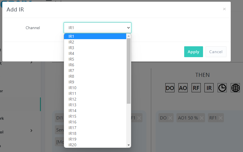
IR options:
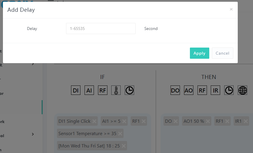
Delay options:
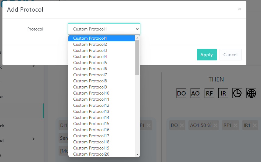
Custom protocol options:
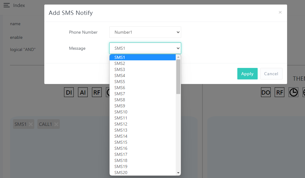
SMS options:
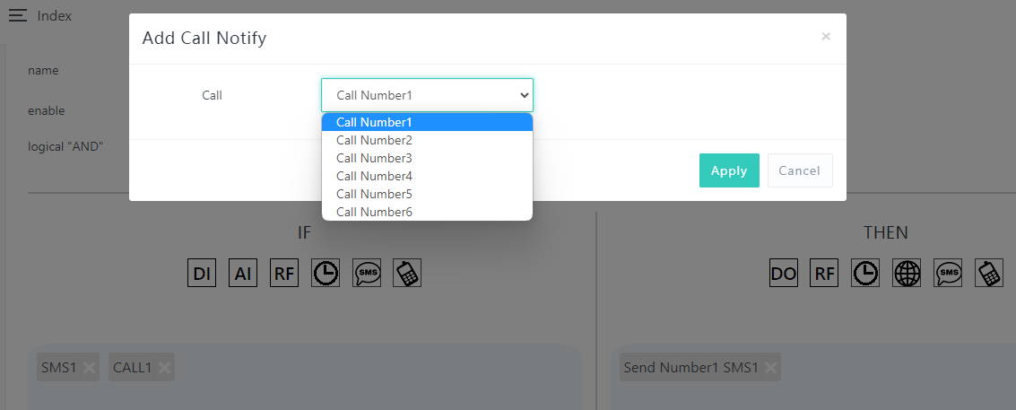
Voice call options:
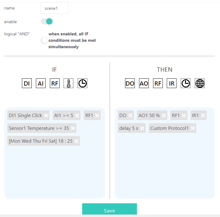
After create completed, you can see all IF and THEN ICO, you can “Save” the AUTOMATION – “scene1” or click small ICO for modify again.
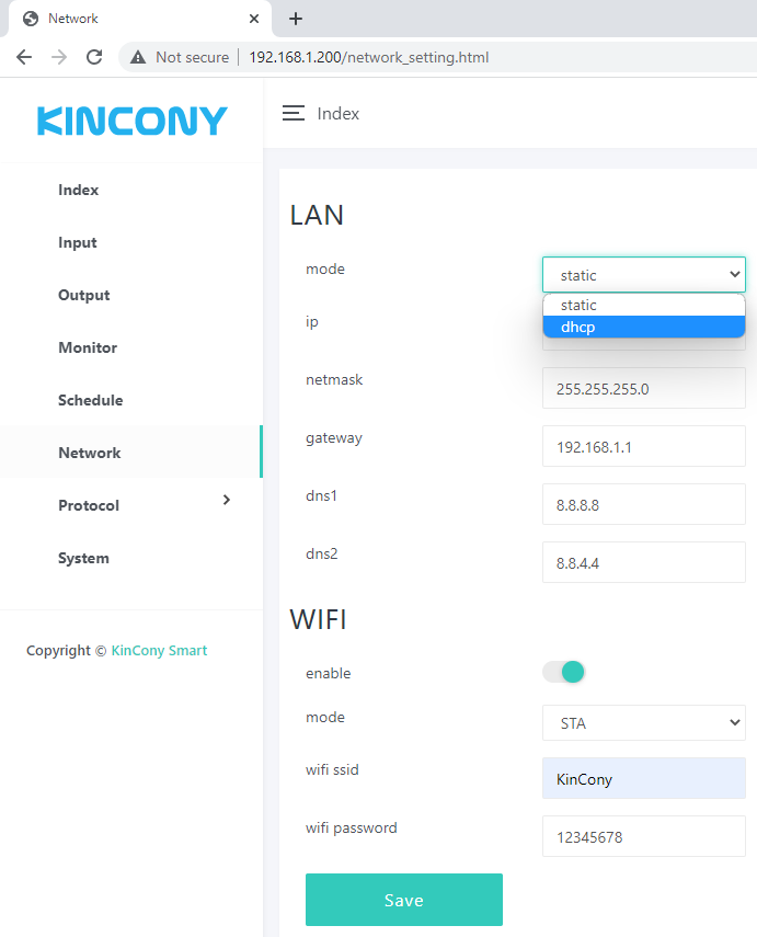
Network setting for ethernet and WiFi.
You if set WiFi by AP mode. device such as mobile phone or tablet can connect to board by wifi directly without wifi router.
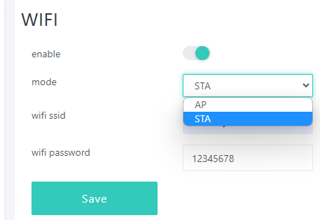
If you set WiFi to STA mode, also you have connect to router by ethernet cable. Board will use ethernet firstly, if ethernet cable disconnected, then will auto switch to WiFi connect to your wifi router, so that make sure let board always connect to your router.
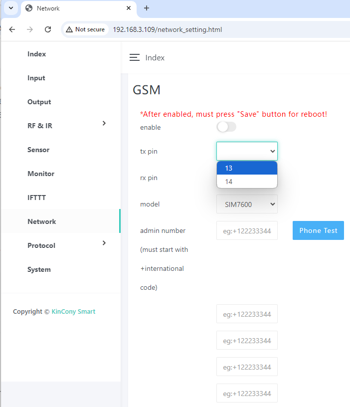
Here is Network – GSM webpage.
You can define extend 4G module RXD, TXD pins, such as for KinCony G1 4G module.
You can enable/disable your GSM module. If disabled, SMS, voice call, GPRS will not work. MAX support fill 6 Administrator Phone Numbers. Only these 6 mobile phone number can use SMS and voice call function. Tuya app with GPRS no mobile phone number limit.
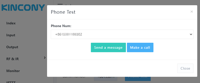
You can select your phone number, then click “Send a message” or “Make a call” for a test.
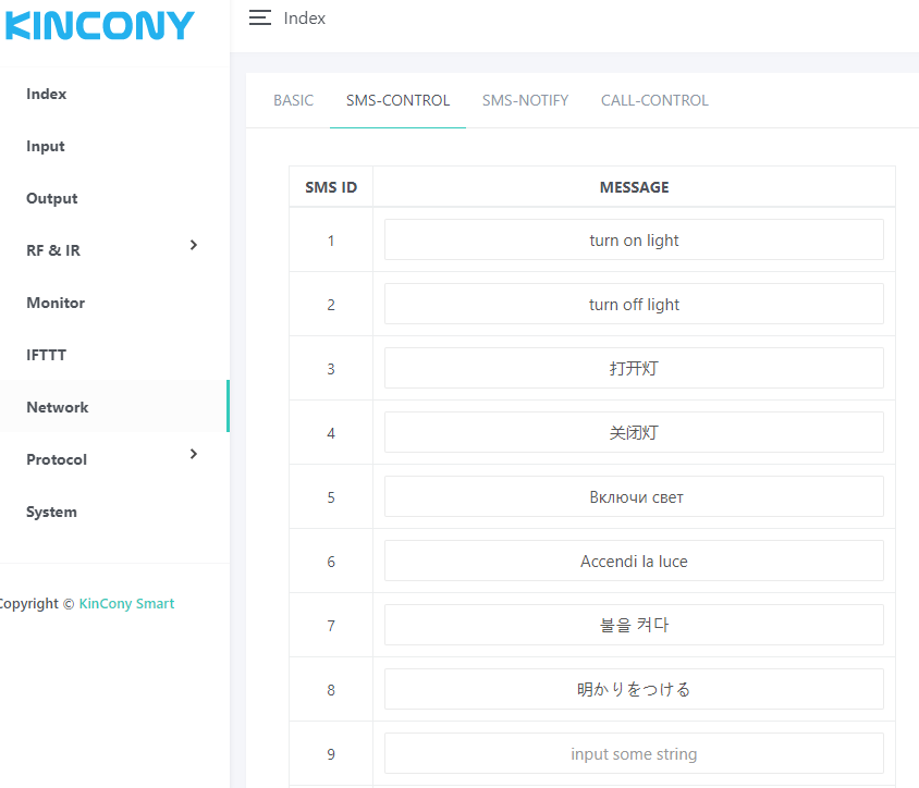
You can define your SMS content use for IF condition. SMS can define by your local language, not only English.
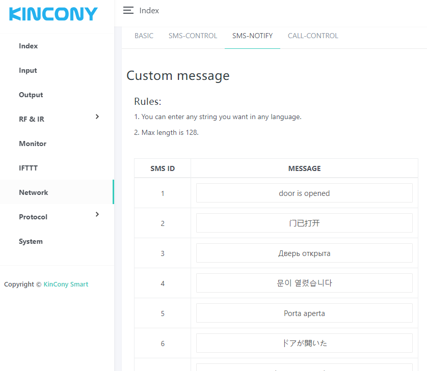
You can define your SMS content use for THEN actions, such as alarm notification. SMS can define by your local language, not only English.
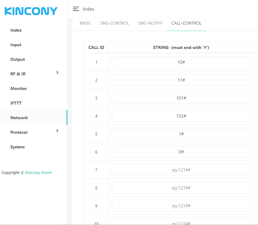
You can define voice call control (DTMF code) for IF condition.
For example: when you voice call your board, when it connected, press key 10# for turn ON relay-1 or press 11# for turn OFF relay-2. Just define a number end with “#”.
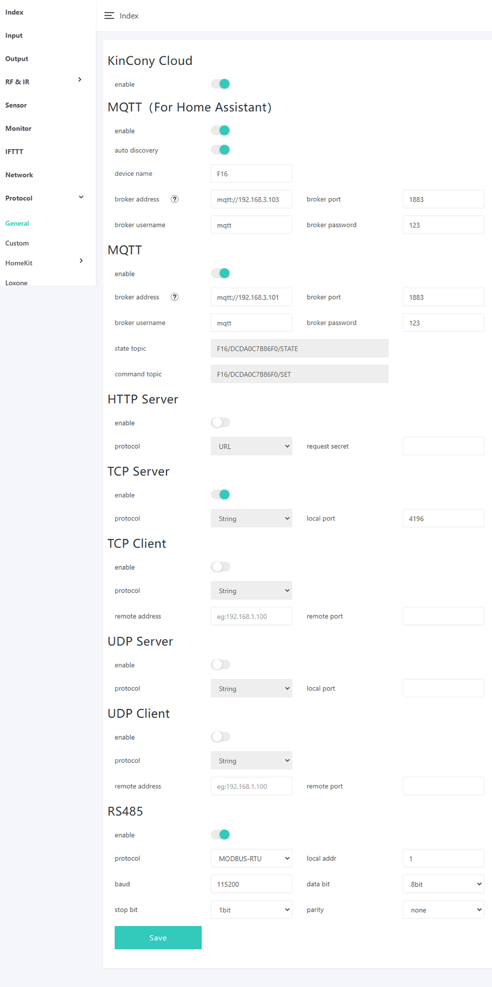
Here is protocol setting webpage. You can enable/disable different protocol in webpage. About these protocol document you can download from KinCony’s webpage.
KinCony Cloud: if you enabled, you can remote control relay or monitor sensor state by web browser using internet.
how to use KinCony Cloud service, please see here
MQTT (For Home Assistant): if you enabled, all board hardware resource will auto discovery by home assistant without any config in home assistant. You only set the mqtt broker’s ip, port, username, password. it’s the easiest way for you to use home assistant and KCS web serivce at the same time.
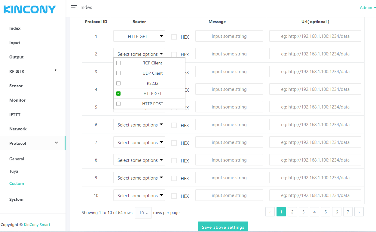
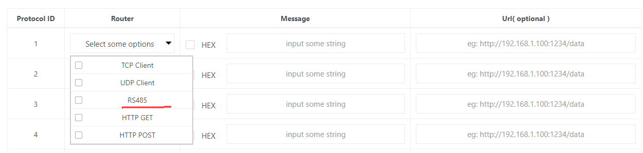
Here is custom protocols webpage.
You can create message for TCP Client, UDP Client, RS232, RS485, HTTP GET, HTTP POST different ways.
If “HEX” options is not checked, will send message by ANSI String.
Fox example:
If you want send a TCP string command to another relay module to turn ON relay1:
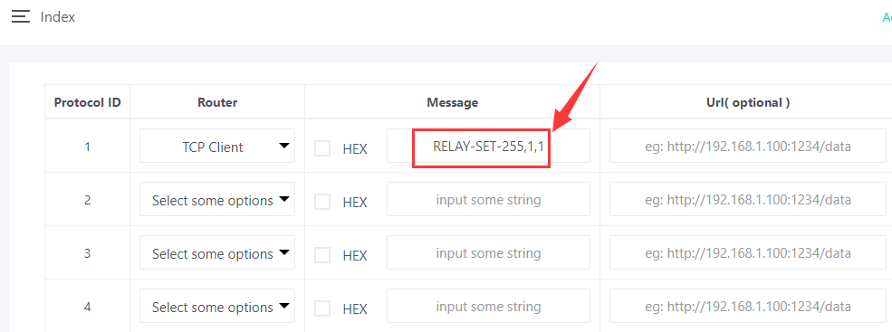
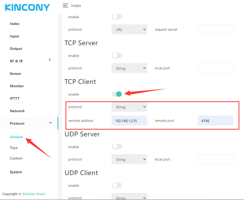
Make sure have enabled TCP Client protocol, remote address: 192.168.1.215 port: 4196 is another relay board.
So the string “RELAY-SET-255,1,1” will send to IP:192.168.1.215 port: 4196 device by TCP.
Fox example:
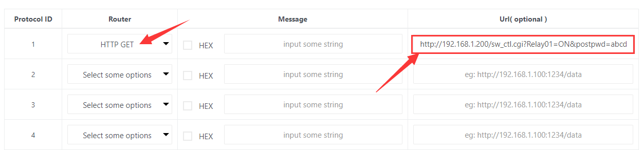
This means:
send HTTP command string
“http://192.168.1.200/sw_ctl.cgi?Relay01=ON&postpwd=abcd” by HTTP GET way. If you need add some message with HTTP command, just fill the “Message” edit box.
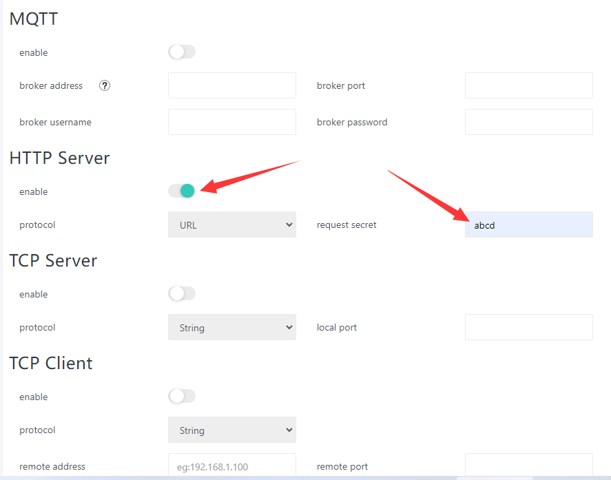
Make sure you can enable the “HTTP Server” protocol and set the “request secret” for safety.
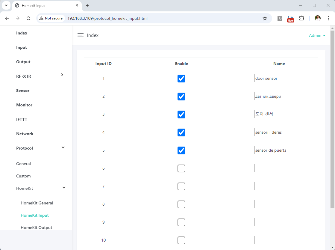
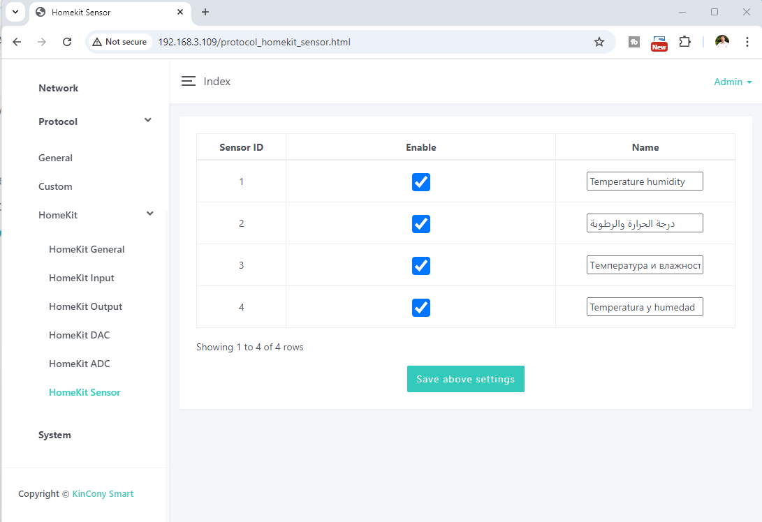
Apple HomeKit:
You can config every device name in Apple HomeKit webpage. How many device you want to enable, just enable the check box. After complete set for INPUT, OUTPUT, DAC, ADC, SENSOR webpage. you just enable the button. Then your iPhone will auto discovery the KinCony device in “HomeKit” APP.

when you use iPhone/iPad add device, the setup code alway fixed by 11122333


If you board have RS485, then the option will list “RS485”.
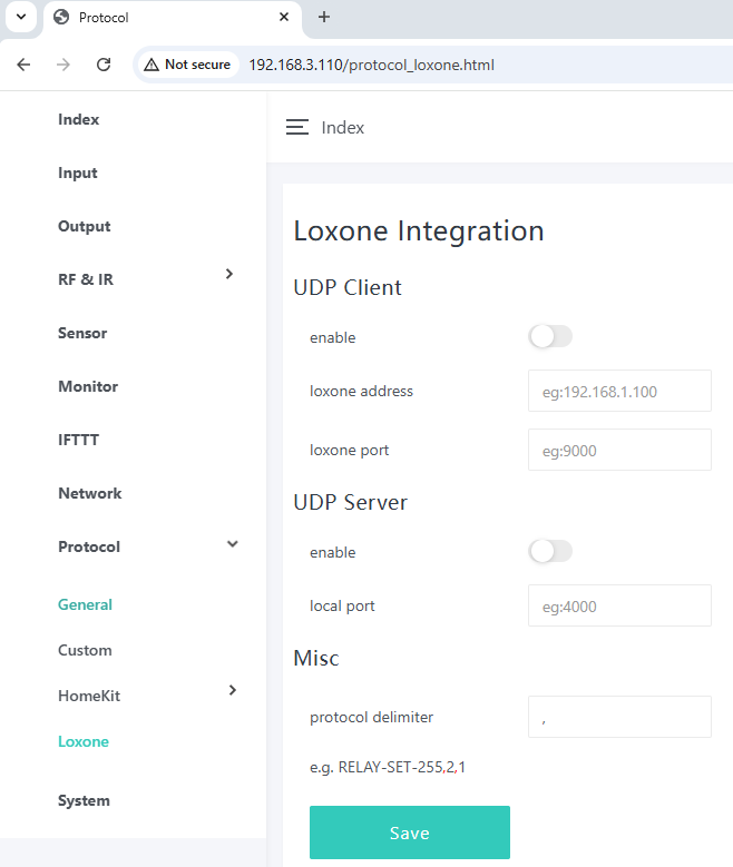
Here is webpage for Loxone Miniserver integration. here is details how to config.
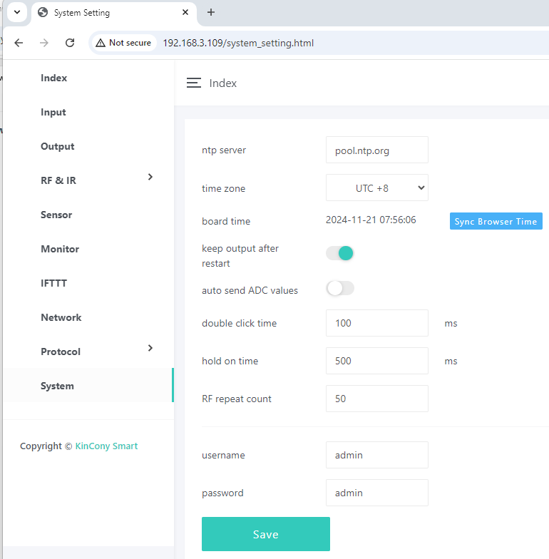
Here is system webpage.
“keep output after restart”: when after power failure, whether auto recovery digital output state when power on again.
“auto send ADC values”: every 5 seconds auto feedback analog input ports value by protocol.
“double click time”: adjust value for change speed of double click.
“hold on time”: adjust value for long or short the hold on time.
Click “sync Browser Time” button, it will write to board’s RTC DS3231 Clock by web browser’s time. So that running IFTTT automation without internet. RTC clock work in locally.
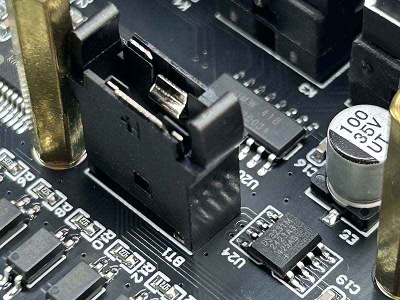
if you want board remember the clock time, you need to install CR1220 battery. the default product without battery inside, because package need send by airplane. Here showed how to install battery.


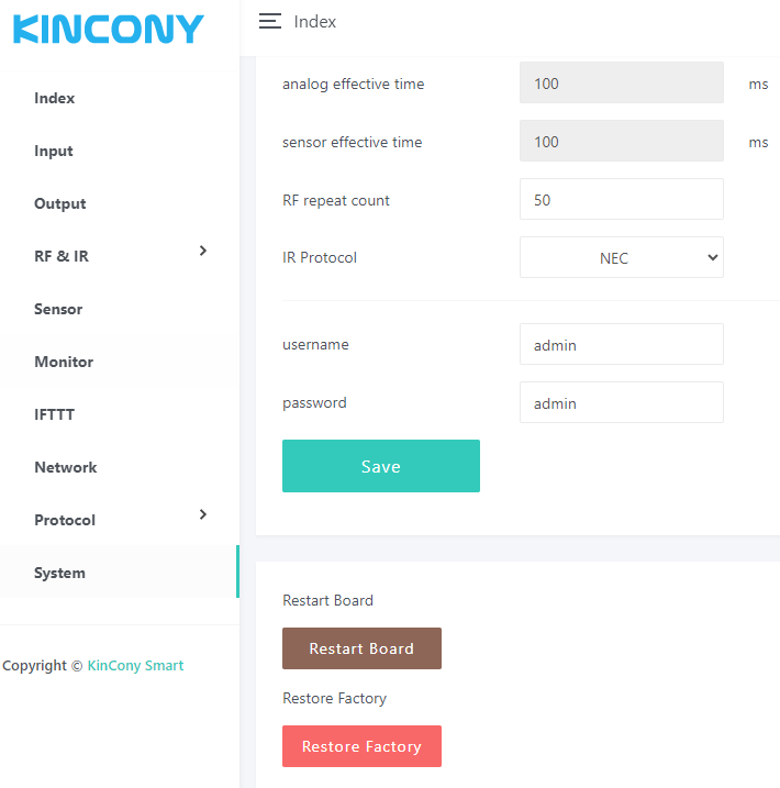
“Restart Board”: reboot board.
“Restore Factory”: clear all setting and set WiFi to “AP” mode.
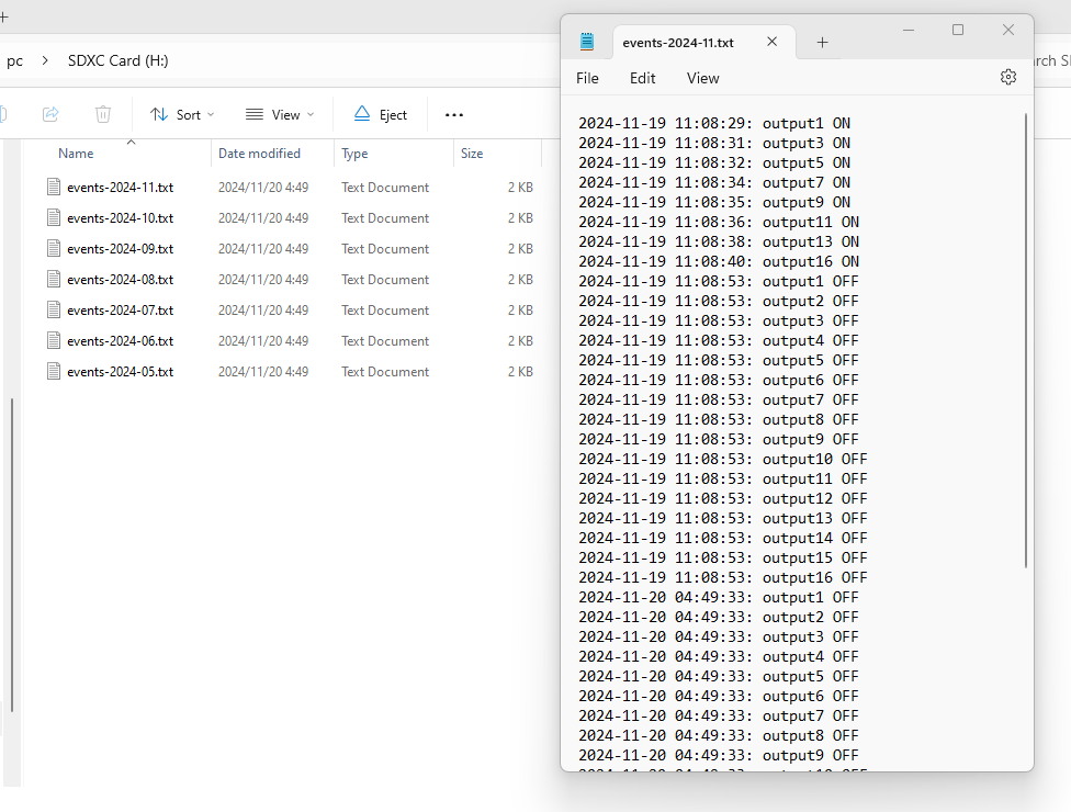
OUTPUT state changed will save to LOG file by SD Card:

If you want to use Tuya mobile phone application (sometimes call smart life app) by remote monitor and control output by internet.
About how to use Tuya phone app: There are two different way to use tuya app.
1. if your controller include Tuya wifi module on PCB, You just use tuya app by mobile phone directly, also support Amazon alexa speaker and google home speaker for voice control directly. here is all steps in details:
Your smart phone or tablet has connected to a 2.4G WiFi with internet.
You need to enable Bluetooth of the phone.
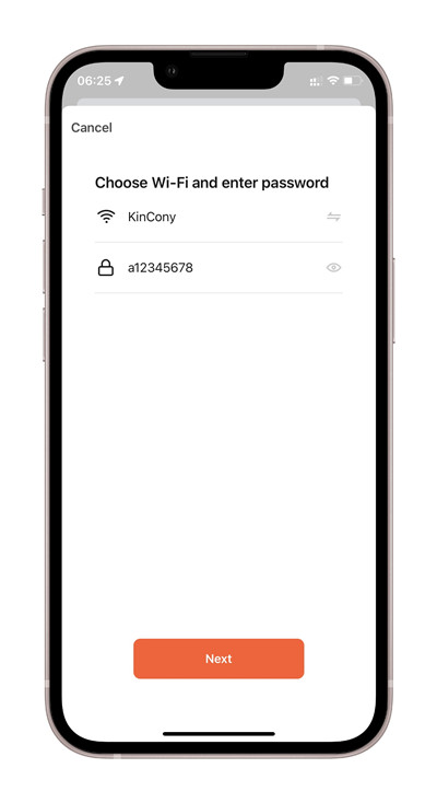
You have the correct router’s WiFi password.
You smart phone or tablet must have access to APP store or Goolge play store.
You router is MAC-open.

You can download the App by searching “Tuya Smart” in mobile phone app stores or scanning the following QR code.
Register an Tuya Smart account. if you already have Tuya Smart account, just login with your username and password.
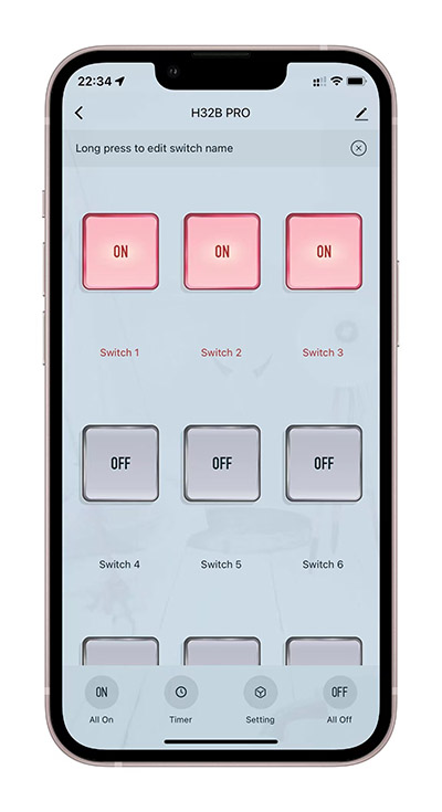
Reset KC868-H32B Pro :
power on of KC868-H32B Pro
hold on “Tuya Mode” button until Green LED fast blinking.
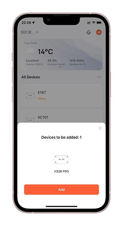
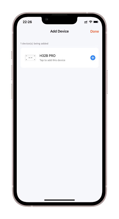
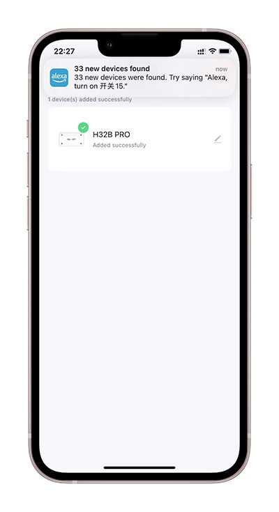
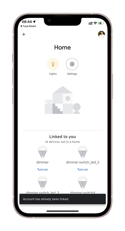
open Tuya App, you will see found “H32B PRO”, or click “Add device” to scan device.
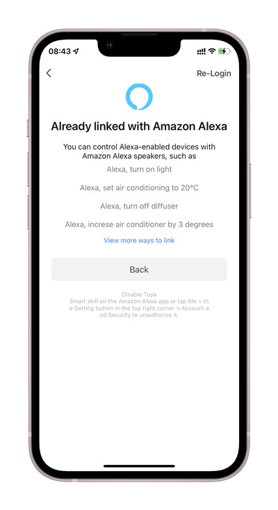
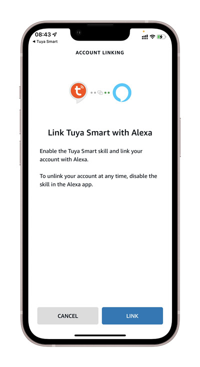
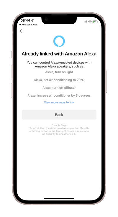
5. How to voice control by Amazon Alexa speaker
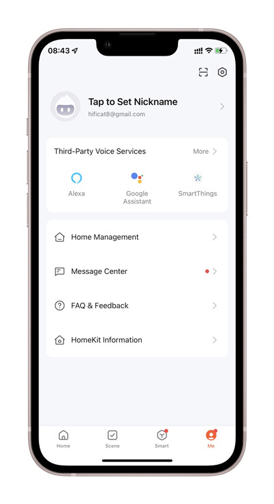
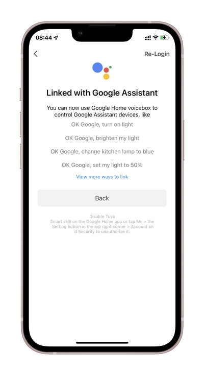
6. How to voice control by Google home speaker
2. if you controller without Tuya wifi module on PCB. You can buy tuya license from us then set in KCS webpage. how to buy tuya license see here
after you got tuya license, you can set in “tuya” webpage:
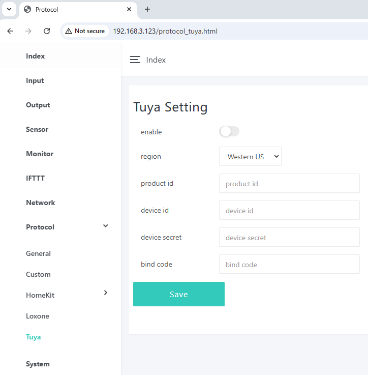
You just fill product id, device id, device secret, bind code to this webpage, make sure NOT paste any SPACE on the end of itmes.
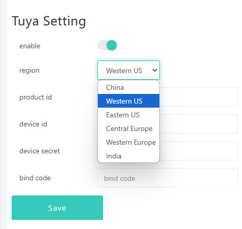
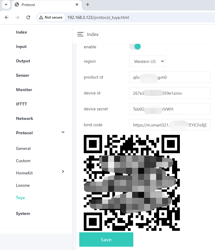
chose server location according to given information. Then it will auto generate QR code, you can scan QR code add board to Tuya mobile phone application.