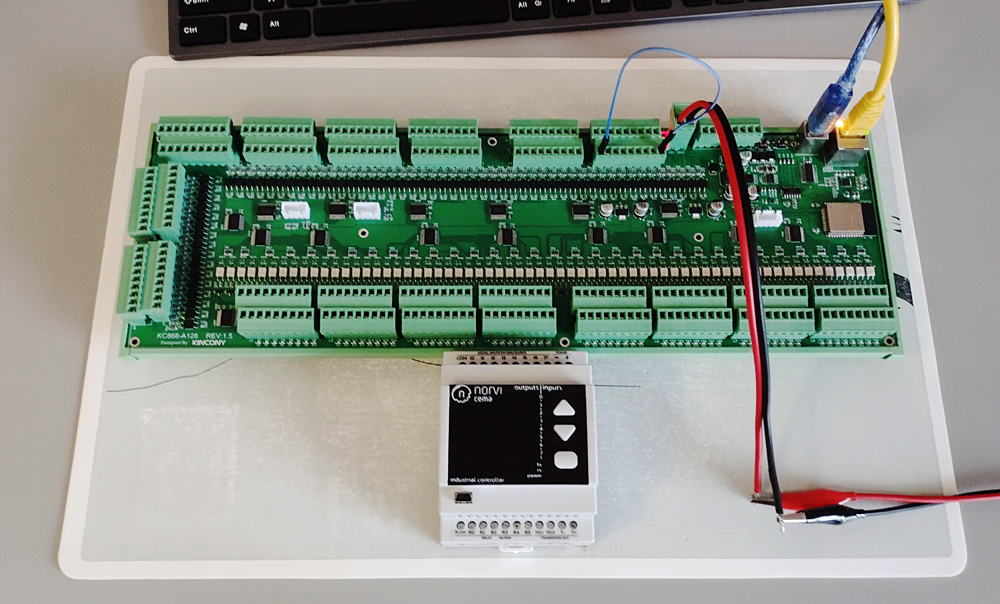
Today we will talk about a solution worthy of placement in the Guinness Book of Records – this is the Kincony KC868-A128 controller, which has as many as 128 digital inputs and 128 digital outputs – transistors (MOSFET) on the board. With such performance characteristics, the KC868-A128 can become the basis of very complex projects. The weak side of such impressive capabilities is the size of the controller – it crosses all boundaries and is somewhat reminiscent of the “wing of an airplane”. KC868-A128 will not fit into any “home” distribution cabinet for automation, for its placement you need either an industrial type of cabinet or some kind of separate box. But it is managed by our favorite and ESP32, which makes it easy to program and create different realizations of project requirements. Now let’s take a closer look at the KC868-A128 and concentrate on controlling all of its 256 inputs/outputs.
❯ Kincony KC868-A128
If we continue with figurative analogies, then the Kincony KC868-A128 can be compared to an ocean container ship – most of the board is occupied by “containers” (elements of digital inputs and MOSFET outputs), and the controller itself (“control booth” – ESP32, Ethernet, etc.) is modestly located on one edge of the board. It is not particularly clear what the main part is and which is the side or input and output elements complement ESP32 or ESP32 complements the inputs and outputs.
Even different ideas emerge: wasn’t it more efficient to divide the controller itself and the hypertrophied I/O unit into two separate devices connected via an I2C interface. In this case, the peripheral units could be connected, depending on the specific task, to the main controller. But these are just fantasies of who prefers what more. Itis easier for Kincony to secure each I/O block with an integrated controller than to realize intercontroller connectors and interfaces.
The KC868-A128 contains:
- Microcontroller ESP32 (ESP-WROOM-32E)
- 128 digital optoisolated inputs (“dry contact”)
- 2 analog inputs 0-5 V
- 2 analog inputs 4–20 mA
- 128 MOSFET output 12/24 V/0.5 A for relay and other control equipment
- 128 output status LED’s
- Connectivity of external relay units KC868-E16 or equivalent
- RS485 interface
- Two separate I2C connectors
- Separate serial port
- Ethernet LAN8270A
- USB port for programming and charging firmware
- Buttons restore and download
- Powered by 12/24 V DC
It is clear that the KC868-A128 has everything it takes to implement a wide range of automation projects, I will not even look in detail at the description of all its subsystems, it will just notice that all this wealth is easy and simple programmable, in my case in the Arduino environment. The application includes the use of KC868-A128 in projects where it is necessary to receive data with multiple inputs and control multiple outputs – actuators.
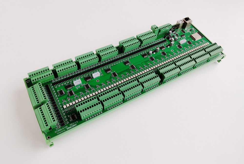
KC868-A128 assembled, ready to be installed on DIN rail (just need to find the right cabinet)
❯ Plug-in relay units
The KC868-A128 uses transistor (MOSFET) outputs that can control not only relays but also other equipment such as solenoid valves. If you want to control the relay, then in this case you need to connect the outdoor units, for example, the Kincony KC868-E16 unit or similar.
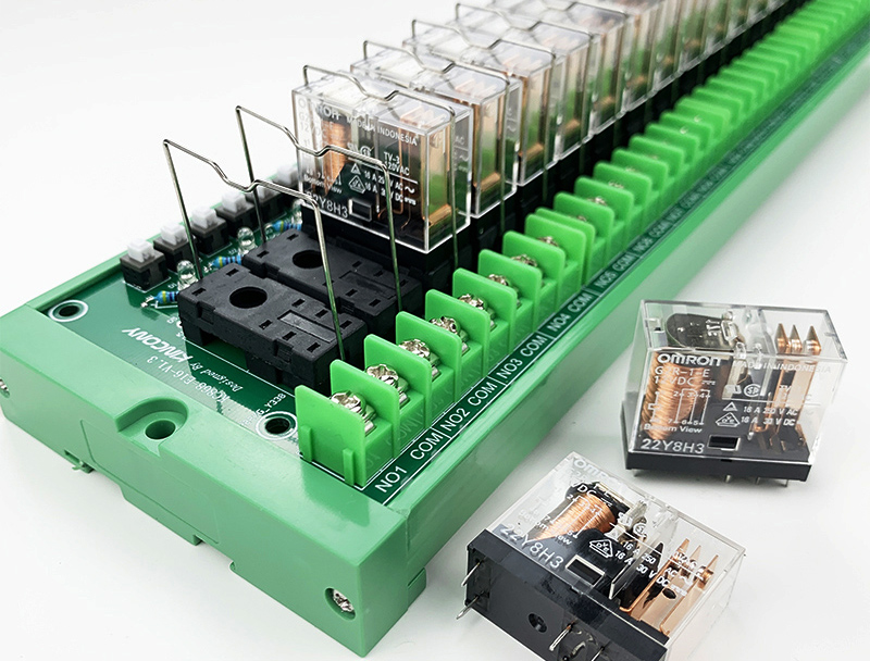
Additional relay unit Kincony KC868-E16
Since the KC868-A128 has 128 outputs, 8 units of KC868-E16 will be required for their full use, or you need to look for multiple relay blocks, such as 32, 64, etc. (if available).
❯ Appearance and design
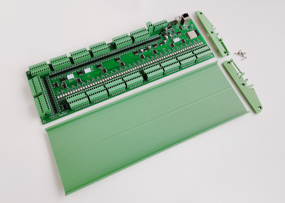
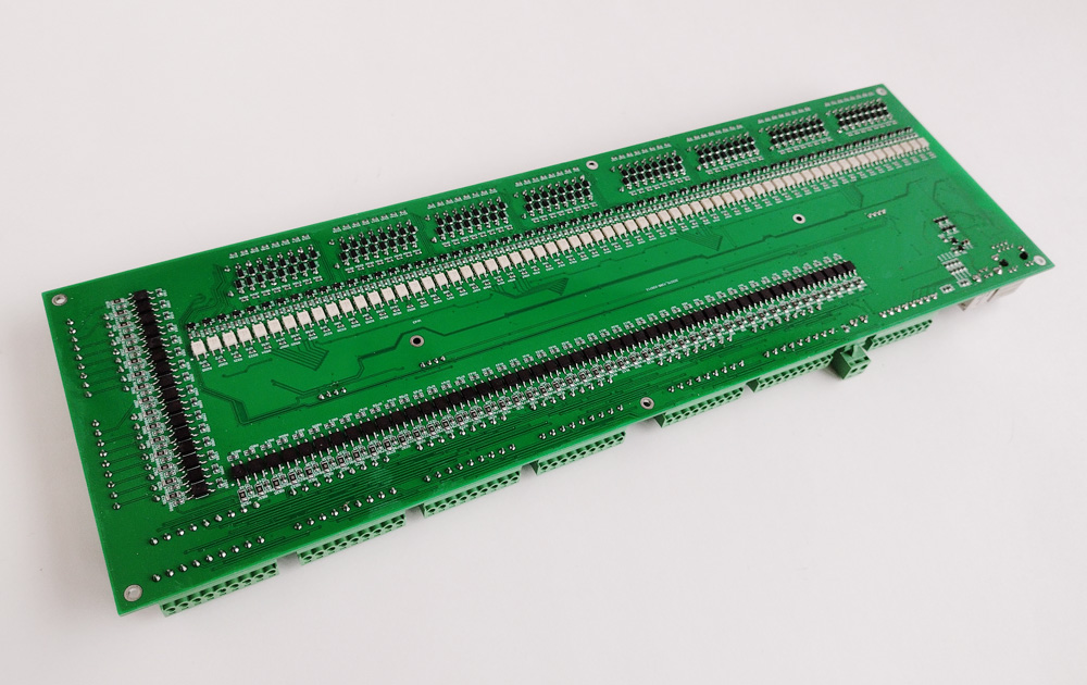
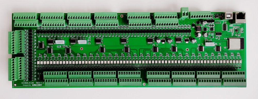
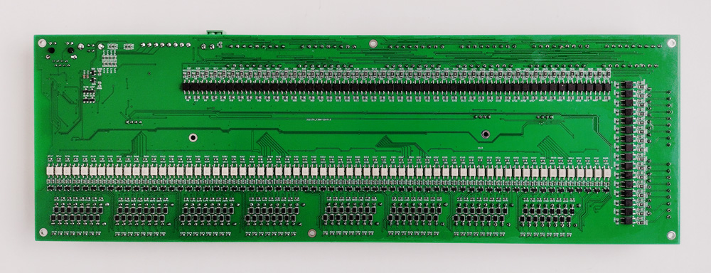
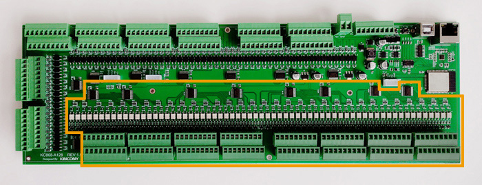
The KC868-A128 is equipped with a special threaded profile for mounting with bolts and for mounting on a DIN rail. Everything is disassembled and simple – it is enough to unscrew a few screws along the edges of this profile and “push” the control panel to the side. Due to the large number of digital inputs and control outputs, not all elements fit on the upper side of the panel. On the back are also optocouplers and MOSFETs.
❯ Circuits
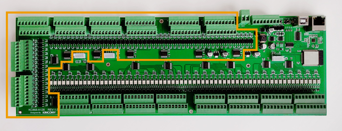
In this section, not all subsystems and controllers KC868-A128 will be presented (Kincony in its products uses standard solutions that are repeatedly described in previous articles), only some of them will be analyzed, characteristic and specific to the model in question. 80% of the board is occupied by inputs / outputs, and the remaining 20% – all other contents of the controller. I wonder if the release of the KC868-A256 will follow and what dimensions the controller will have in this case?
Digital inputs
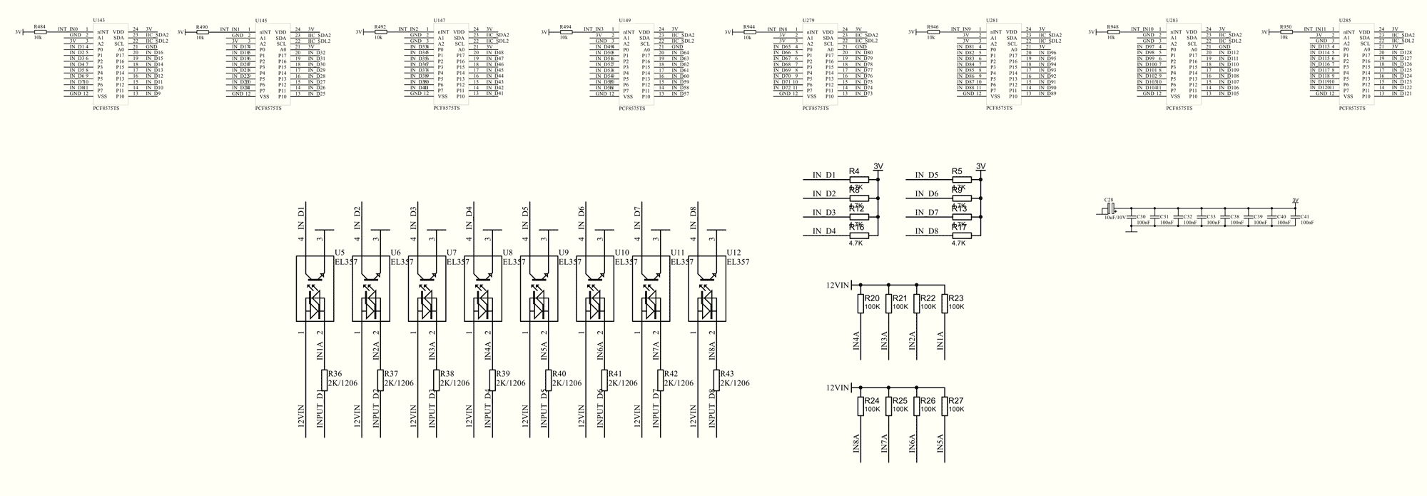
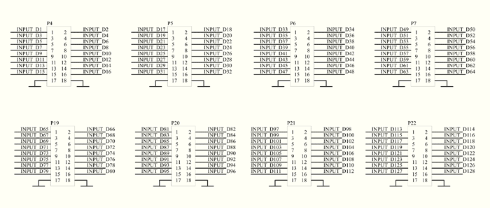
The controller has 128 digital opto isolated “dry contact” inputs on EL357 optocouplers, arranged in 16 connectors with 8 contacts each. To ensure their operation in collaboration with ESP32, the KC868-A128 uses digital I/O extenders with I2C interface on 8 PCF8575TS chips. For clarity and in order not to clutter up the scheme, only one of the 16 blocks of optocoupler is shown, the others are exactly equal. The connector extenders to the PCF8575TS display all 8 connectors digital input them and one of the two I2C interfaces (I2C No. 2). Separately, the connector scheme for connecting digital optoinsulated inputs “dry contact”. Each connector has two GND contacts (to close).
MOSFET outputs
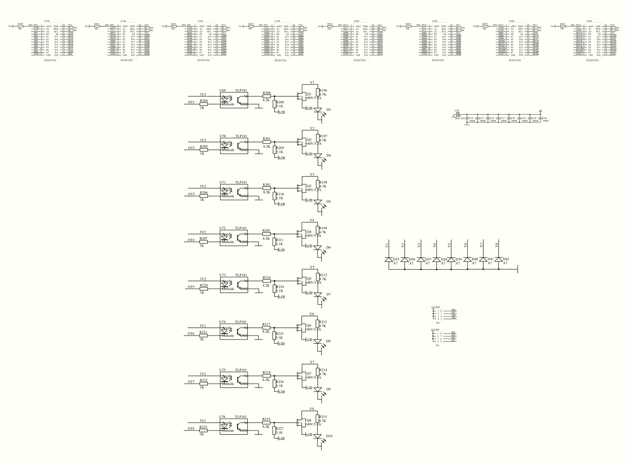
Another large subsystem of the KC868-A128 controller, the interaction of which with the ESP32 microcontroller is carried out using an 8 I/O expander with i2C interface PCF8575TS. Furthermore, control signals are received on TLP181 optocouplers, which control 128 MOSFET transistors NCE40P05Y (40V/5.3A). There are also indicator LEDs, by which you can determine the current state of the output of the controller KC868-A128. The diagram shows only one of the 16 MOSFET blocks (the others are exactly the same to him). Output control is carried out through the I2C interface (I2C No1). Each connector has a contact to connect a power supply voltage of 12/24 V.

I2C links
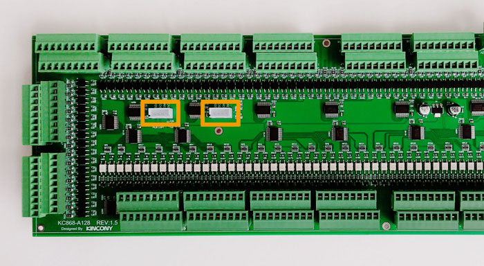
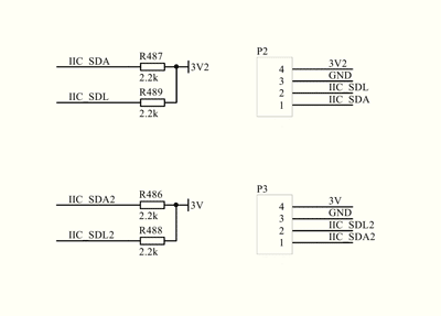
Two very useful things for connecting different additional components of I2C connectors. You can connect to them, for example, a display, additional sensors and other elements. Moreover, keep in mind that these connectors have different interfaces (I2C No1 and I2C No2). Schematic diagram of subsystems (connectors) I2C:
Serial connector
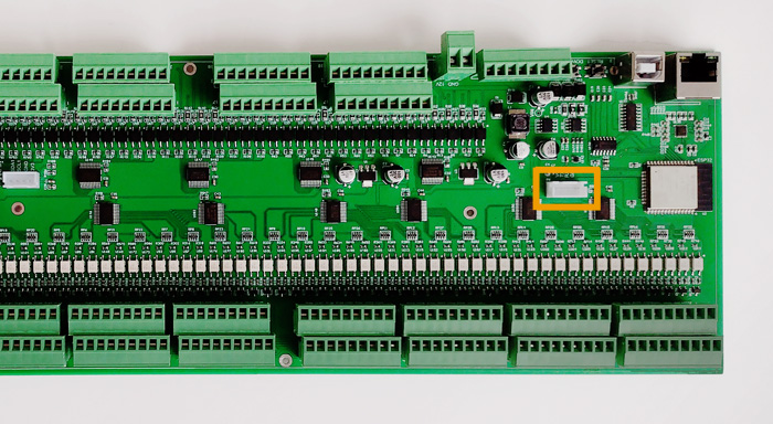
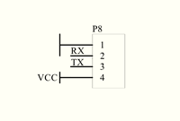
No less useful accessory – you can connect a lot of interesting equipment to this connector, which uses a serial interface to receive and transmit data. Schematic diagram of a serial subsystem (connector):
Pin layout
Comprehensive information about what is and how connected to the ESP32 microcontroller on the KC868-A128 board.
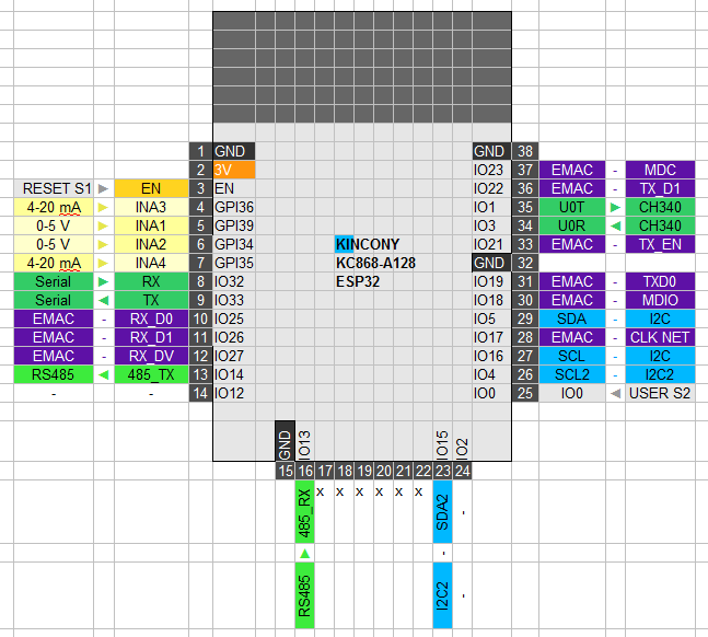
❯ Controller scheme
The original scheme of connectors and external connections of the controller KC868-A128 manufacturer. Here you can clearly see all the locations and pinouts of the connectors.
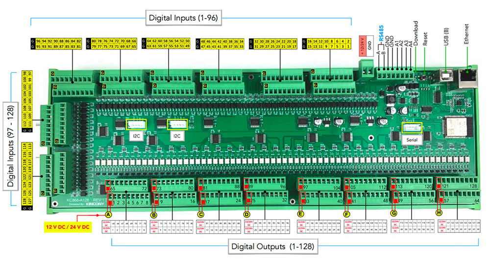
❯ Programming
Now let’s look at some examples of programming KC868-128. Since the pcf8575 I2C port extender chips are used to control the digitalm inputhas and the MOSFET outputhas, we will need the appropriate PCF8574_library to work with them.
Programming digital inputs
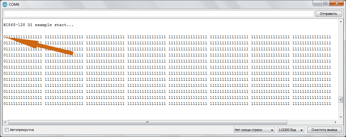
For example, let’s imagine receiving data from all 128 digital inputs controller KC868-A128 and send that data to the serial port. To make sure our program really works, we’ll close the first digital entry to the ground, with a jumper this should be reflected in the output data.
/*
QC868-A128 DI example
*/
#include “Arduino.h”
#include “PCF8575.h”
#define SDA 15
#define SCL 4
PCF8575 pcf_1(0x24, SDA, SCL);
PCF8575 pcf_2(0x25, SDA, SCL);
PCF8575 pcf_3(0x21, SDA, SCL);
PCF8575 pcf_4(0x22, SDA, SCL);
PCF8575 pcf_5(0x26, SDA, SCL);
PCF8575 pcf_6(0x27, SDA, SCL);
PCF8575 pcf_7(0x20, SDA, SCL);
PCF8575 pcf_8(0x23, SDA, SCL);
void setup() {
Serial.begin(115200);
Serial.println();
Serial.println(F(“KC868-128 DI example start…”));
pcf_1.begin();
pcf_2.begin();
pcf_3.begin();
pcf_4.begin();
pcf_5.begin();
pcf_6.begin();
pcf_7.begin();
pcf_8.begin();
for (byte i = 0; and < 16; i++) {
pcf_1.pinMode(s), INPUT);
pcf_2.pinMode(s), INPUT);
pcf_3.pinMode(s), INPUT);
pcf_4.pinMode(s), INPUT);
pcf_5.pinMode(s), INPUT);
pcf_6.pinMode(s), INPUT);
pcf_7.pinMode(s), INPUT);
pcf_8.pinMode(s), INPUT);
}
delay(1000);
}
void loop() {
Serial.println();
for (byte i = 0; and < 16; i++) {Serial.print(pcf_1.digitalRead(i));} Serial.print(‘ ‘);
for (byte i = 0; and < 16; i++) {Serial.print(pcf_2.digitalRead(i));} Serial.print(‘ ‘);
for (byte i = 0; and < 16; i++) {Serial.print(pcf_3.digitalRead(i));} Serial.print(‘ ‘);
for (byte i = 0; and < 16; i++) {Serial.print(pcf_4.digitalRead(i));} Serial.print(‘ ‘);
for (byte i = 0; and < 16; i++) {Serial.print(pcf_5.digitalRead(i));} Serial.print(‘ ‘);
for (byte i = 0; and < 16; i++) {Serial.print(pcf_6.digitalRead(i));} Serial.print(‘ ‘);
for (byte i = 0; and < 16; i++) {Serial.print(pcf_7.digitalRead(i));} Serial.print(‘ ‘);
for (byte i = 0; and < 16; i++) {Serial.print(pcf_8.digitalRead(i));} Serial.print(‘ ‘);
delay(300);
}
Example KC868-A128 DI
*/
#include “Arduino.h”
#include “PCF8575.h”
#define SDA 15
#define SCL 4
PCF8575 pcf_1(0x24, SDA, SCL);
PCF8575 pcf_2(0x25, SDA, SCL);
PCF8575 pcf_3(0x21, SDA, SCL);
PCF8575 pcf_4(0x22, SDA, SCL);
PCF8575 pcf_5(0x26, SDA, SCL);
PCF8575 pcf_6(0x27, SDA, SCL);
PCF8575 pcf_7(0x20, SDA, SCL);
PCF8575 pcf_8(0x23, SDA, SCL);
null setup() {
Serial start(115200);
Serial.println();
Serial.println(F(“KC868-128 DI example start…”));
pcf_1.begin();
pcf_2.begin();
pcf_3.begin();
pcf_4.begin();
pcf_5.begin();
pcf_6.begin();
pcf_7.begin();
pcf_8.begin();
for (byte i = 0; and < 16; i++) {
pcf_1.pinMode(s), INPUT);
pcf_2.pinMode(s), INPUT);
pcf_3.pinMode(s), INPUT);
pcf_4.pinMode(s), INPUT);
pcf_5.pinMode(s), INPUT);
pcf_6.pinMode(s), INPUT);
pcf_7.pinMode(s), INPUT);
pcf_8.pinMode(s), INPUT);
}
delay(1000);
}
void loop() {
Serial.println();
for (byte i = 0; and < 16; i++) {Serial.print(pcf_1.digitalRead(i));} Serial.print(‘ ‘);
for (byte i = 0; and < 16; i++) {Serial.print(pcf_2.digitalRead(i));} Serial.print(‘ ‘);
for (byte i = 0; and < 16; i++) {Serial.print(pcf_3.digitalRead(i));} Serial.print(‘ ‘);
for (byte i = 0; and < 16; i++) {Serial.print(pcf_4.digitalRead(i));} Serial.print(‘ ‘);
for (byte i = 0; and < 16; i++) {Serial.print(pcf_5.digitalRead(i));} Serial.print(‘ ‘);
for (byte i = 0; and < 16; i++) {Serial.print(pcf_6.digitalRead(i));} Serial.print(‘ ‘);
for (byte i = 0; and < 16; i++) {Serial.print(pcf_7.digitalRead(i));} Serial.print(‘ ‘);
for (byte i = 0; and < 16; i++) {Serial.print(pcf_8.digitalRead(i));} Serial.print(‘ ‘);
delay(300);
}
Since the KC868-128 board has an I2C interface that runs on non-standard GPIO15 and 4 (I2C #2), we need to explicitly state this in the program.
We immediately get the addresses (0x24, 0x25, 0x21, 0x22, 0x26, 0x27, 0x20, 0x23) of the PCF8575 connector extender.
#define SDA 15
#define SCL 4
PCF8575 pcf_1(0x24, SDA, SCL);
PCF8575 pcf_2(0x25, SDA, SCL);
PCF8575 pcf_3(0x21, SDA, SCL);
PCF8575 pcf_4(0x22, SDA, SCL);
PCF8575 pcf_5(0x26, SDA, SCL);
PCF8575 pcf_6(0x27, SDA, SCL);
PCF8575 pcf_7(0x20, SDA, SCL);
PCF8575 pcf_8(0x23, SDA, SCL);
Then we initialize the expansion lines as the input and print in the loop the matrix of all 128 digital inputs KC868-128 (note zero in the first position of each row – this is the first input connected to the GND). This is a very complex device, not like most that contains a few digital inputs and outputs.
Programming output
Let’s try to program the second KC868-128 chip now – that’s 128 MOSFET outputs. Just imagine an electrical panel on which 128 relays or 128 valves are connected to the controller.
/*
KC868-A128 DO example
*/
#include “Arduino.h”
#include “PCF8575.h”
#define SDA 5
#define SCL 16
PCF8575 pcf_1(0x24, SDA, SCL);
PCF8575 pcf_2(0x25, SDA, SCL);
PCF8575 pcf_3(0x21, SDA, SCL);
PCF8575 pcf_4(0x22, SDA, SCL);
PCF8575 pcf_5(0x26, SDA, SCL);
PCF8575 pcf_6(0x27, SDA, SCL);
PCF8575 pcf_7(0x20, SDA, SCL);
PCF8575 pcf_8(0x23, SDA, SCL);
void setup() {
Serial.begin(115200);
Serial.println();
Serial.println(F(“KC868-128 DO example start…”));
pcf_1.begin();
pcf_2.begin();
pcf_3.begin();
pcf_4.begin();
pcf_5.begin();
pcf_6.begin();
pcf_7.begin();
pcf_8.begin();
for (byte i = 0; and < 16; i++) {
pcf_1.pinMode(s), OUTPUT);
pcf_2.pinMode(s), OUTPUT);
pcf_3.pinMode(s), OUTPUT);
pcf_4.pinMode(s), OUTPUT);
pcf_5.pinMode(s), OUTPUT);
pcf_6.pinMode(s), OUTPUT);
pcf_7.pinMode(s), OUTPUT);
pcf_8.pinMode(s), OUTPUT);
}
delay(1000);
}
void loop() {
Serial.println();
pcf_1.digitalWrite(P0, HIGH); Serial.println(F(“OUT1 HIGH”));
delay(3000);
pcf_1.digitalWrite(P0, LOW); Serial.println(F(“OUT1 LOW”));
delay(3000);
}
Here everything is similar to maintaining digital inputs, only PCF8575 chips are connected to 1. I2C (GPIO5, 16). Then initialize the objects and configure the lines as outputs.
#define SDA 5
#define SCL 16
PCF8575 pcf_1(0x24, SDA, SCL);
PCF8575 pcf_2(0x25, SDA, SCL);
PCF8575 pcf_3(0x21, SDA, SCL);
PCF8575 pcf_4(0x22, SDA, SCL);
PCF8575 pcf_5(0x26, SDA, SCL);
PCF8575 pcf_6(0x27, SDA, SCL);
PCF8575 pcf_7(0x20, SDA, SCL);
PCF8575 pcf_8(0x23, SDA, SCL);
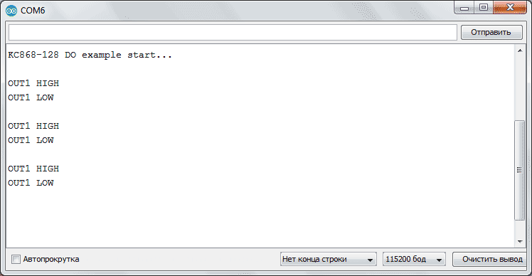
Then, in the loop, we control one (first) output, on and off. Similarly, any of the 128 outputs on the KC868-128 board can be controlled.
❯ Conclusion
Now that you can get data with a hundredth inand more sensors and control a hundred and more actuators in a project, you know what to do in such large projects. What’s best is the ease of programming the KC868-128 can easily program as much as you want to control the equipment and communicate over different protocols with your IoT automation system.
In addition to the emphasis on 128 digital inputs and 128 outputs, it should not be forgotten that the KC868 A128 also has 4 analog inputs:
- 2 analog inputs 0-5 V
- 2 analog inputs 4–20 mA
Which can significantly enrich the application of this controller on complex projects. Thus, projects with exclusively switching functions can be enhanced with the monitoring of 4 analog quantities via analog sensors.
We wish you a successful application, and if you send us your interesting projects, we will be happy to publish them and share them with others.


