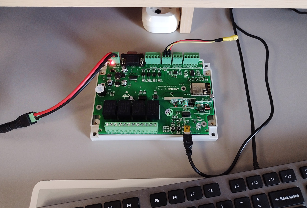
One long winter evening, I would sit in front of a monitor and browse the internet for anything interesting in general and anything interesting in particular. Unfortunately, the Internet was not very pleased with anything special and I came across either the already stuffed standard debug boards, or variations on the theme “box with ESP8266 / ESP32 with 1-4 relays”. ESP32 with a 4th relay is, of course, good, but I wanted something more and then I came across the Kincony KC868-A4 board. Not bad! I thought and put on my glasses to get a better look at it…
Kincony KC868-A4
Upon closer inspection, the Kincony KC868-A4 board turned out to be a very nice device. The core on the ESP32 with a set of peripheral modules integrated on the board. There is a set of relays, and opto-isolated digital inputs, analog inputs and outputs, the ability to connect a temperature and humidity sensor (sensors), integrated modules at 433 MHz, an infrared receiver and emitter, an RS232 connector and even a piezoelectric squeaker (a trifle, but nice). And all this is packed into a complete commercial solution, framed in normal connectors and has the possibility of installation in a high-quality housing on a DIN rail.
A small lyrical digression. At one time, Arduino revolutionized and made microcontroller technology available to everyone. It’s wonderful and just wonderful, but for some reason unknown to me, all arduino equipment manufacturers do not want to take the next logical step – to produce the same Arduino, but in the form of complete devices (which you can program for your own needs) and ready for use in real projects.
In this sense, the Kincony KC868-A4 is a step in the right direction – it is a complete device that you can install on the DIN rail, connect the wires to the (normal!) connectors and program for your own needs. When using Kincony KC868-A4, you do not need to “collectivelyze” anything from individual wiring and blue insulating tape – the difference with the usual Arduino-DIY is enormous – this is a completely different level, especially for real projects. We’ll talk about this in more detail later, but we can say about the Kincony KC868-A4 that in general it is a fairly balanced device for use in small projects, as well as for the purpose of learning to program microcontrollers and other similar purposes.
Kincony KC868-A4 Cycle Plan
It is impossible to review such a device as kincony KC868-A4, and even more qualitatively to review, in one article, so I have divided all the material into several logically separate articles:
Part 1. Overview and hardware (this article). A general overview of the Kincony KC868-A4 and a detailed analysis of the circuitry of this controller.
Part 2: Programming components. Kincony KC868-A4 contains about a dozen subsystems and in this article we will analyze the programming of its individual parts (working with inputs, DAC, relay control, wireless modules, etc.).
Part 3: Advanced examples. Here it is planned to give a description and code of advanced examples of working with Kincony KC868-A4, like controlling the controller through a Telegram bot or Whatsapp, etc.
Part 4. Firmware for Kincony KC868-A4. Here it is planned to analyze an example of installing on this controller and using some ready-made firmware, like Tasmota, ESPhome or a specialized version of AMS, etc. This is a minimum set of articles that will be included in the series, but the topic of Kincony KC868-A4 is very extensive and in the process of working on articles new ideas may appear and then this cycle can be expanded with other materials about this controller. If this is of interest to Habra’s audience, you can run a series of articles on the more advanced Kincony KC868-A8 and KC868-A16 controllers and analyze the ethernet control issues of ESP32 and other advanced functions of these controllers.
Components и characteristics
Now let’s see what the Kincony KC868-A4 has on board. This, of course, is the ESP32 module in the ESP32-S modification (an analogue of esp-WROOM-32 from Ai-Thinker). And, accordingly, this module brings all the functionality of ESP32 to the Kincony KC868-A4. These are Wi-Fi, Bluetooth, two cores and the corresponding set of pins and interfaces, plus 4 MB of built-in EEPROM memory.In addition to the ESP32 module, the Kincony KC868-A4 board contains:
- 4 digital opto-untied inputs (“dry contact”)
- 2 analog inputs 0-5 V
- 2 analog inputs 4–20 mA
- 2 analog outputs (DAC) 0–10 V
- 4 relays 10A 220V
- Connector for connecting a temperature or humidity sensor
- DB9 RS232 connector
- 433 MHz receiver/transmitter modules
- Infrared (IR) receiver and transmitter
- Piezoceramic buzzer
In general, a good set of integrated peripherals, which allows you to create a huge number of different projects on this board. Of the conditional shortcomings of this set can be called a small number of inputs / outputs and the lack of free pins for connecting additional peripherals. But if the capabilities of kincony KC868-A4 cover the needs of your project, then you just need to connect the wires and pour the appropriate firmware – and the board will begin to control the connected equipment.
Product line
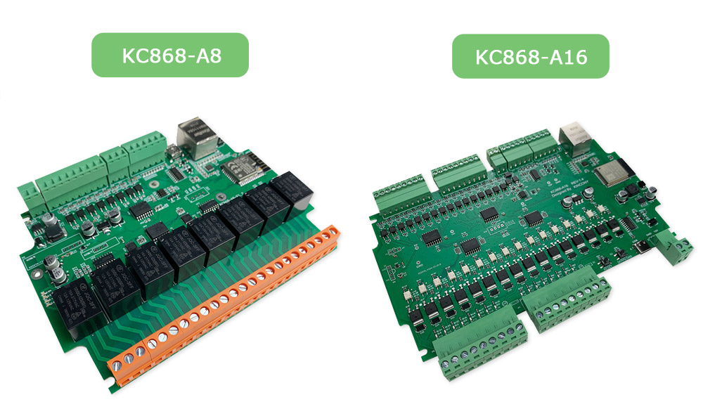
Judging by the website and products, Kincony is a very creative company with far-reaching plans. In their assortment there are many different controllers from the simplest to the most expensive and complex, and you can choose the right controller for the tasks of your project. Kincony KC868-A4 has two big brothers – the KC868-A8 and KC868-A16 boards. These are more advanced solutions with a wider range of possibilities. From the younger brother, they differ not only in the number of inputs and relays integrated into the board, but also in the ability to connect and work via Ethernet network, as well as the ability to use two interfaces simultaneously – wireless Wi-Fi and wired Ethernet and other functions.
Body and equipment
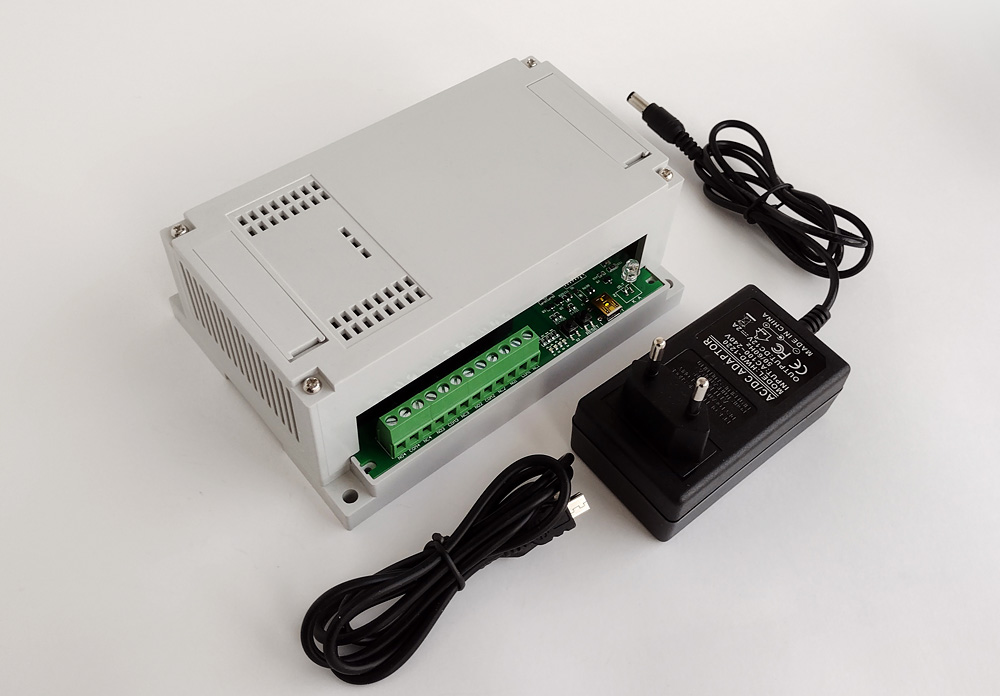
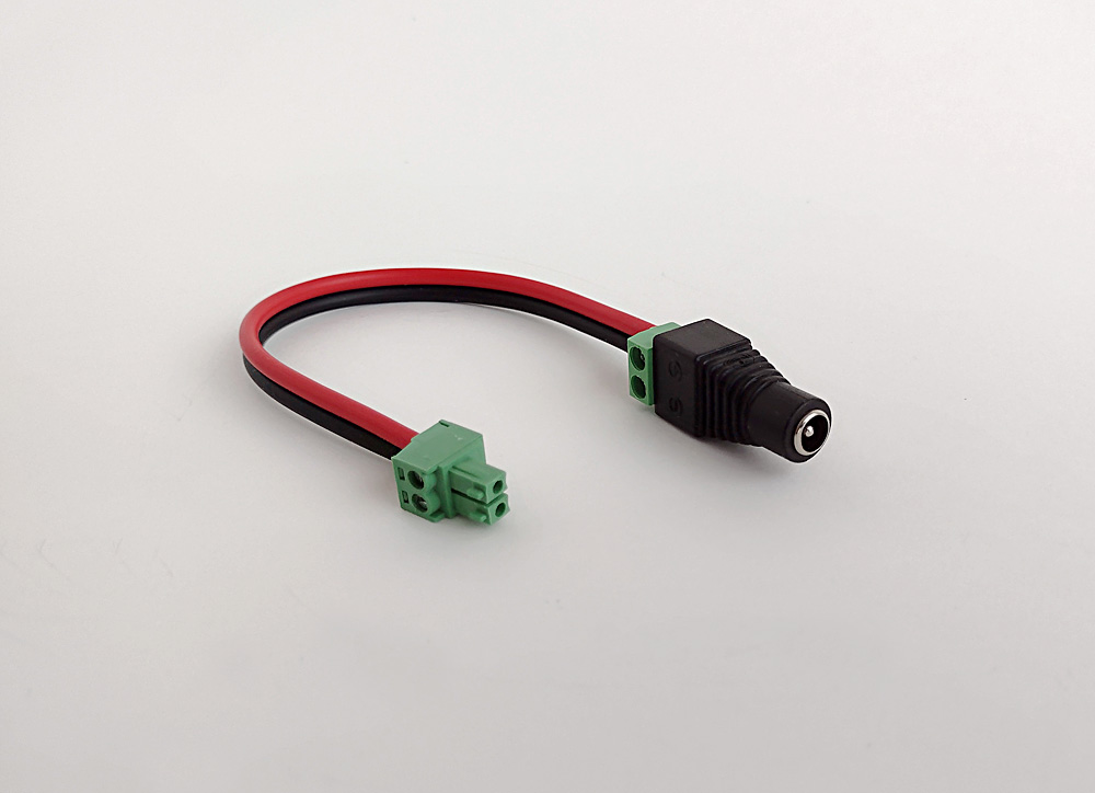
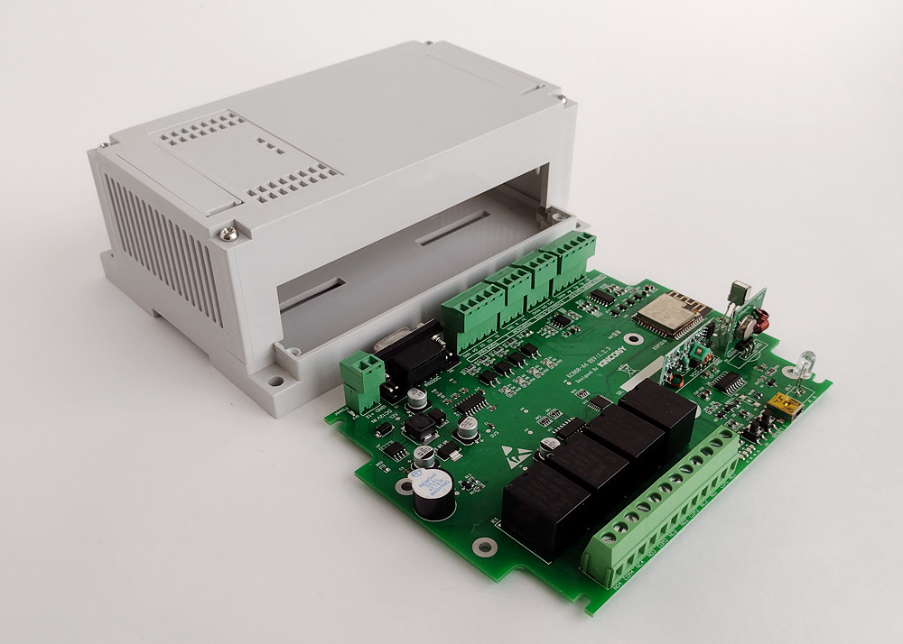
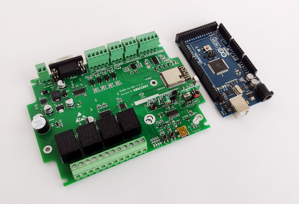
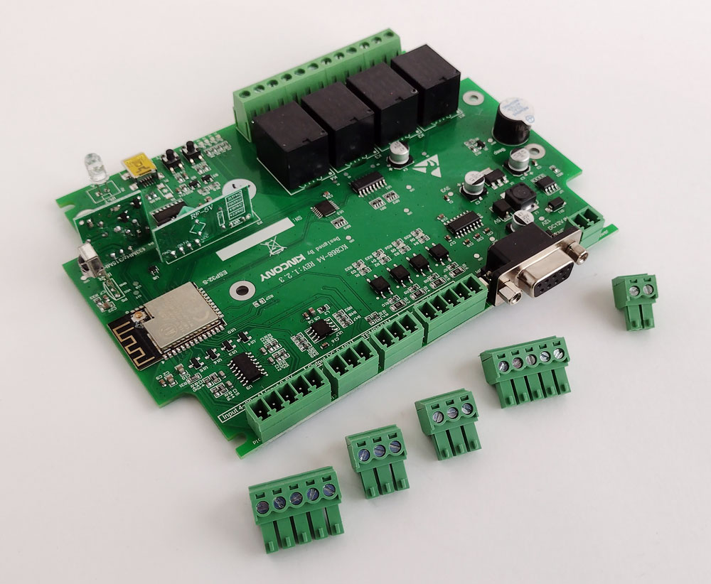
Kincony KC868-A4 is sold both in the form of a separate board (at, in my opinion, a fairly affordable price), and in the form of various kits based on it: with a power supply, radios, case, etc. In my case, I preferred to buy the most complete set so as not to “collective farm” anything and immediately start working with the device. But one “jamb” still allowed: in the kit there is a power supply with a “round” power connector a la Arduino, and the board has a connector for twisting wires with screws. Therefore, I still had to “shake the old” and make an adapter for connecting the power supply to the board. Here you have complete freedom of action – you can use the Kincony KC868-A4 separately in any of your cases, you can use the “native” case for installation on the DIN-rail or not install it on the rail, but simply screw it to any suitable surface. Kincony KC868-A4 board in comparison with the standard and beloved Arduino Mega 2560. At the same time, you can estimate how much more convenient (and more correct) it is to use kincony KC868-A4 in some real project. Here you have a built-in power module, and normal connectors for connecting wires, and a relay unit, and an indication of the status of inputs and outputs, etc. By the way, not simple connectors are installed on the board, but connectors with removable pads, which makes the work even more convenient.
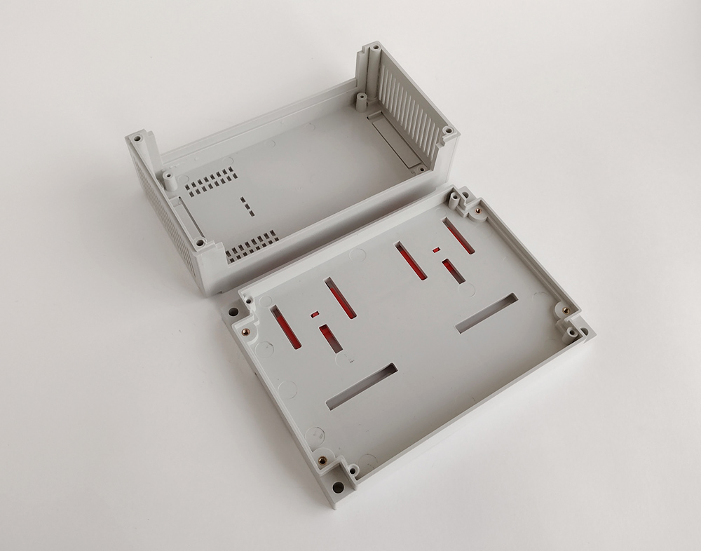
A little more about the case
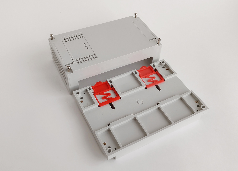
Kincony KC868-A4 comes with a high-quality case – it looks normal, is made of high-quality plastic and has a well-thought-out geometry, in the sense of conveniently located holes for fastening, as well as plugs and holes on the front panel – in general, the case left a very pleasant impression. Also in the photo you can see the plugs for displaying the GPOI connectors and a template-window for buttons and indicators on the front panel.
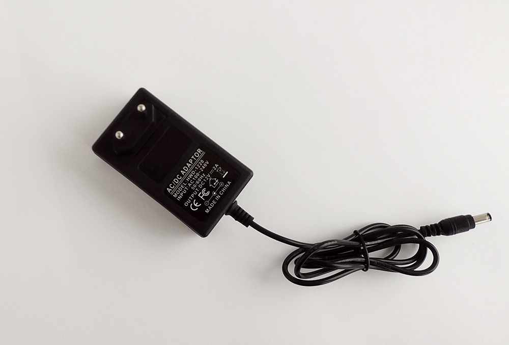
Power supply unit
Controller Kincony KC868-A4 comes with a power supply 12 V / 2 A. I did not test the quality of the power supply, I just did not see the need for it – there are no problems with the operation of the controller from this power supply.However, given the specifics of the controller itself, I have thoughts about using some kind of UPS option for uninterrupted power supply Kincony KC868-A4.
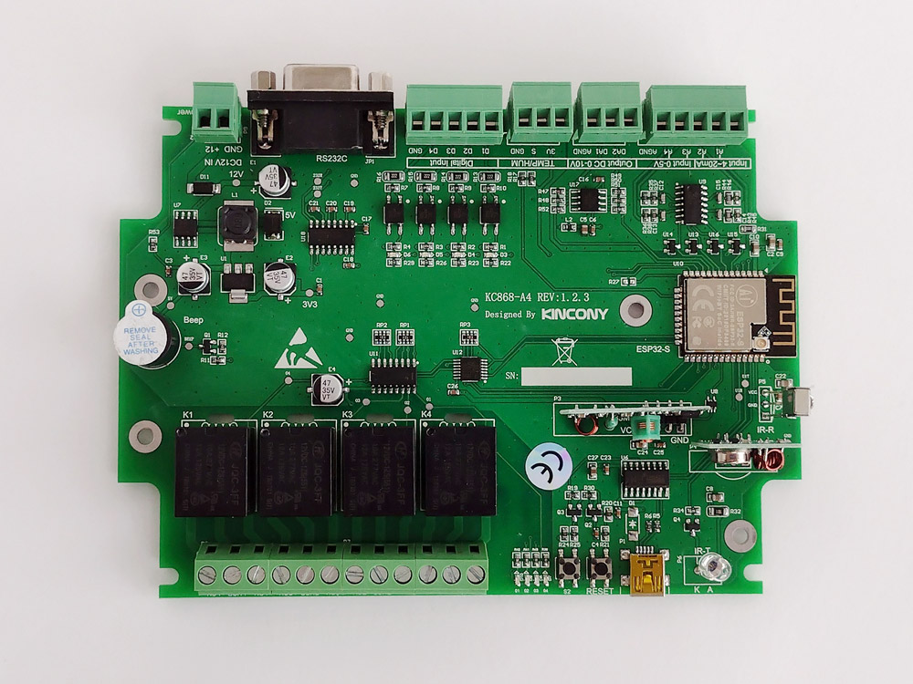
Kincony KC868-A4 Board
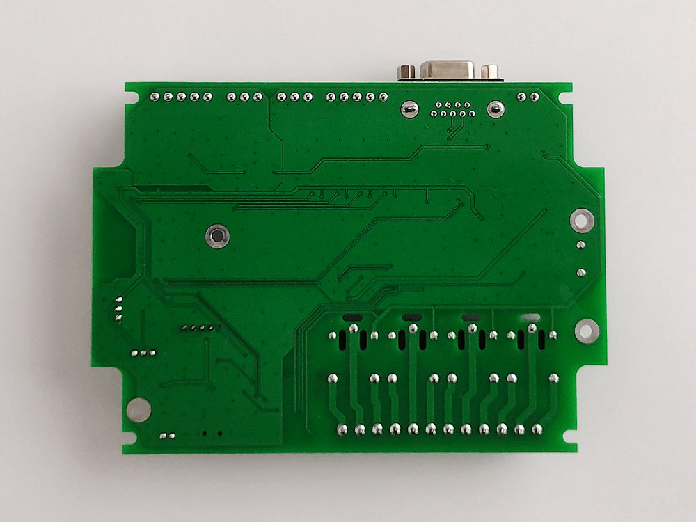
Now let’s proceed to the analysis of the controller board itself. To get started, a top view of the installed components.Bottom view. The lower part of the board is completely devoid of any details. Wide relay line paths and milled holes to protect against electrical breakdowns are also visible. How competently the board is divorced and how well the protection against breakdowns is performed, we will be told by professional “ironclads” Habra (we will not deprive them of this opportunity).
Circuit technology
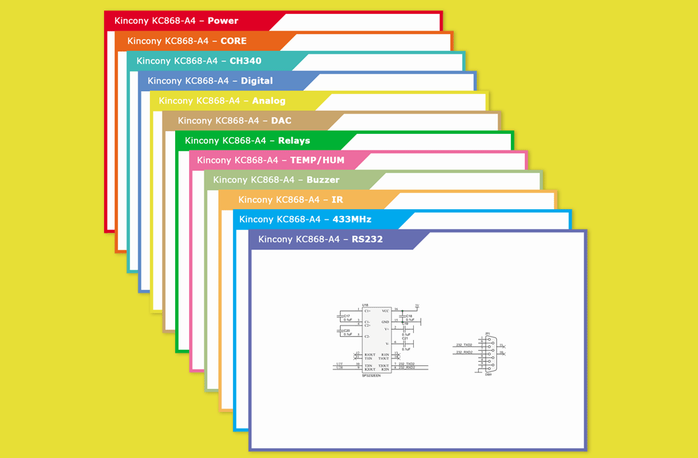
We will consider the circuitry according to the following principle: the visual designation of a particular functional subsystem of the controller, its schematic diagram and my brief comments about the subsystem itself, its features and the errors / shortcomings identified during the testing process. I suggest in the comments to speak on the circuit design and solutions used by the manufacturer Kincony KC868-A4 – how good / bad, from your point of view, and if you see any errors or weaknesses, how they could be improved.
▍ Power supply
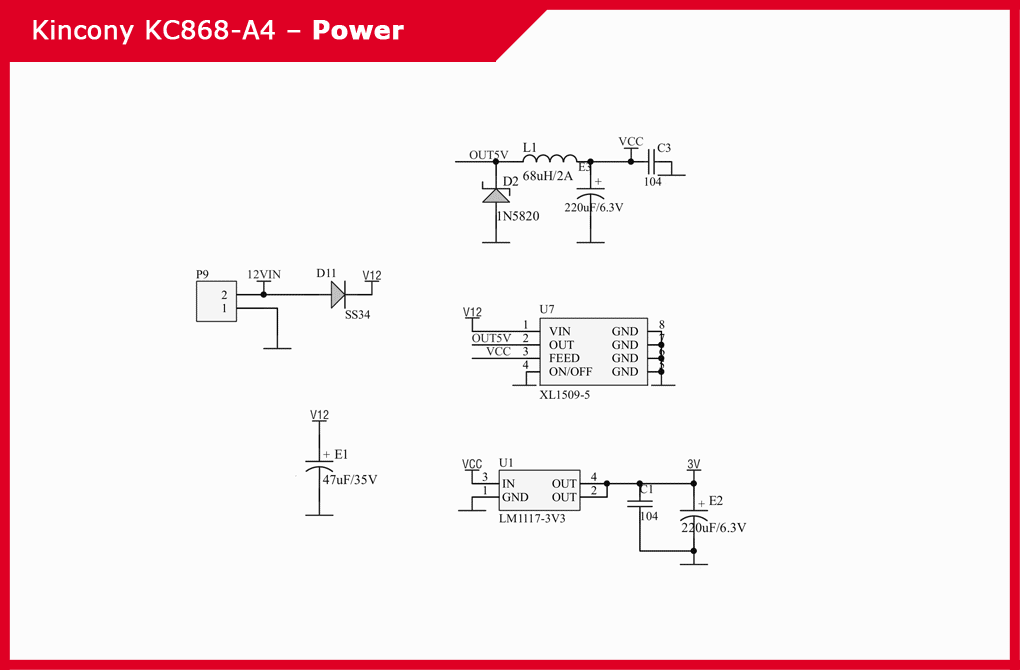
The power subsystem is quite simple, to form an in-circuit voltage of 5 V from the input voltage 12 V, the developers of Kincony KC868-A4 used a chip step-down DC-DC converter XL1509-5, and to form a voltage of 3.3 V – a linear regulator LM117-3V3.

▍ ESP32 core
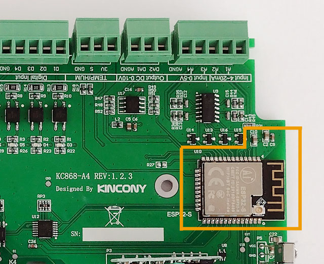
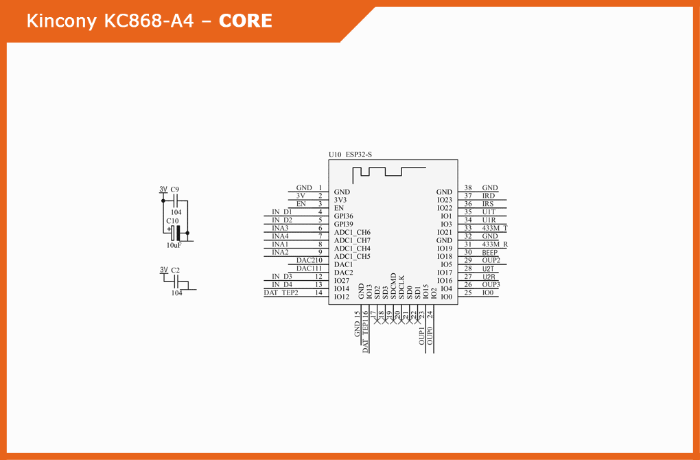
As the core of the controller Kincony KC868-A4 used module ESP32-S, which we have already talked about earlier. The composition of this functional unit includes 3 more filter capacitors located in the immediate vicinity of ESP32.The antenna, although located within the board, but on both sides is deprived of proximity to the tracks to avoid shielding and deterioration of the quality of communication. Also on the ESP32-S module it is possible to resolder the jumper and connect an external antenna instead of the built-in one.Schematic diagram and pinout of the core (ESP32) of the controller:
▍ USB/CH340
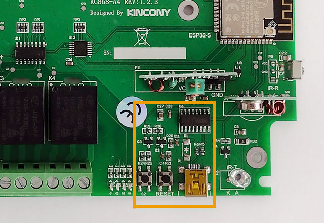
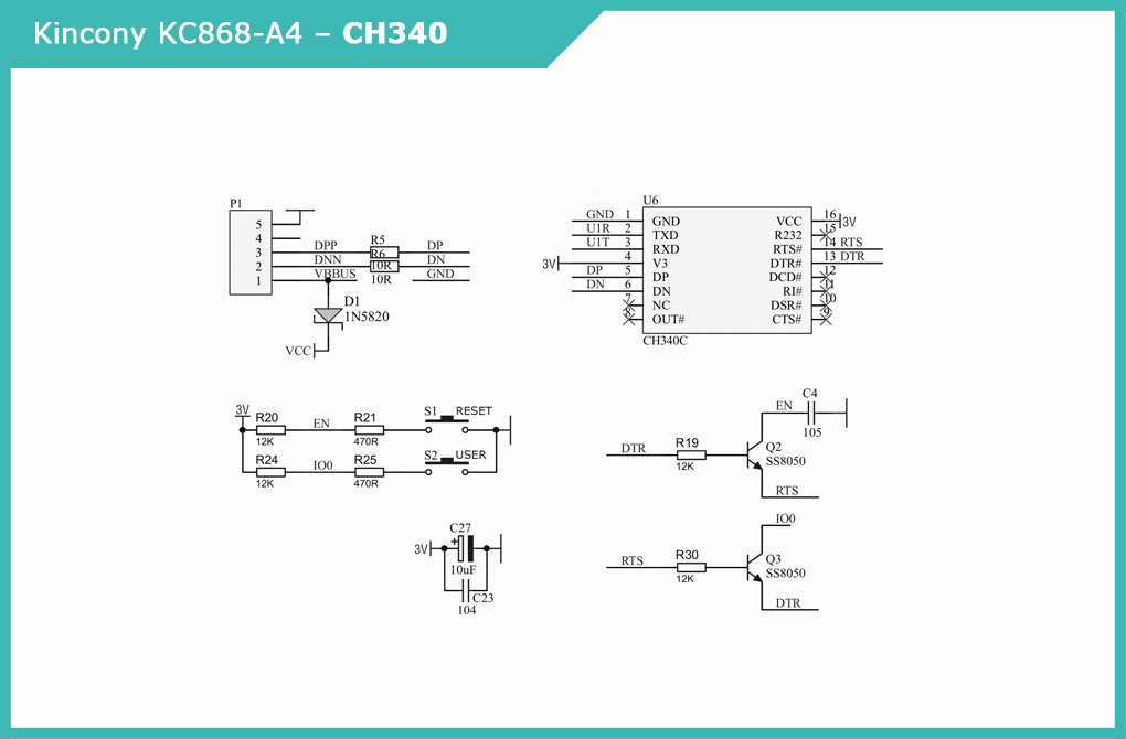
To connect to a computer, program and fill firmware in ESP32 on the board there is a Mini-USB connector and a chip USB / Serial converter CH340C, as well as the corresponding harness and two buttons – “RESET” and programmable “USER”. By the way, the photo shows that the manufacturer for some reason did not solder on the board D1. Schematic diagram of the subsystem USB/CH340 controller:
▍ Digital inputs
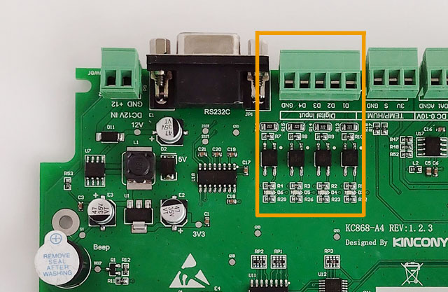
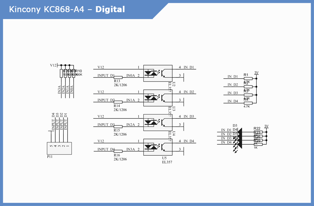
The Kincony KC868-A4 board has 4 digital “dry contact” inputs, for the opto-isolation of which EL357 optocouplers and the corresponding strapping are used. Also on each channel there is an LED, which is very convenient because you can immediately see in what condition each of the four digital inputs of the board is.
▍ Analog inputs
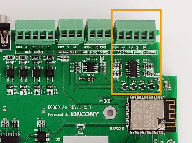
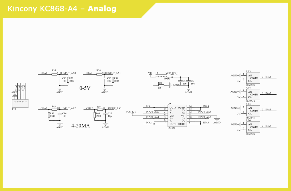
The Kincony KC868-A4 has 4 analog inputs divided into two groups: 0-5 B and 4-20 mA signals. Signal formation is handled by input stages connected to the LM324 quadruple op-amp. Then there are twin Schottky diodes BAT54S and then the signals go directly to the inputs of the ESP32 microcontroller.Pay attention to a small section of the circuit that forms the voltage of the 12V_1 and the “analog ground” AGND for analog inputs and outputs (DAC).Schematic diagram of the analog input subsystem:
▍ DAC
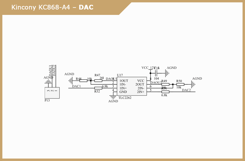
The formation of analog output signals 0-10 V is engaged in a dual operational amplifier TLC2262C with the appropriate strapping and power supply from 12V_1 / AGND. Circuit diagram of the DAC subsystem of the controller:

▍ Relays
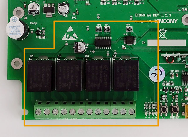
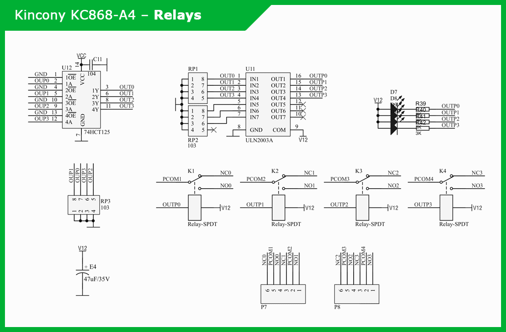
Kincony KC868-A4 has on board 4 relays, for which the formation of control signals is carried out by the chip 74HCT125 with four drivers and the matrix of Darlington transistors ULN2003A. The board also has 4 LEDs to indicate the current status of each relay.Schematic diagram of the relay subsystem:
▍ Temperature/humidity sensors
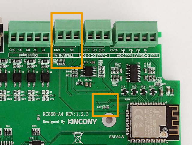
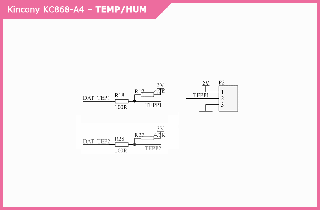
Contacts for connecting the temperature sensor are displayed on the pad 3V, S, GND. By default, the DS18B20 temperature sensor should be connected to this pad. But no one prevents you from connecting to these contacts a network of several DS18B20 sensors, an air humidity sensor or any other sensor suitable for the type of connection – it all depends on the software you use. You just need to remember that the board has already soldered the resistor of the lift to the supply voltage of 3.3 V.Regarding the connection of the temperature sensor to the Kincony KC868-A4 board. Here, Kincony had some kind of failure and there were discrepancies between the circuit diagram and the real board, its tracks and soldered components. The documentation contains two channels, TEMP1 and TEMP2, but in reality there is only one channel temp1 on the board. Also in the documentation mentions a pad for connecting temperature sensors with 4 pins, and in reality there is a 3-pin pad on the board. On the board there is also a wiring for the resistor R27, but the resistor itself is not soldered.Schematic diagram of the subsystem for connecting temperature and humidity sensors:
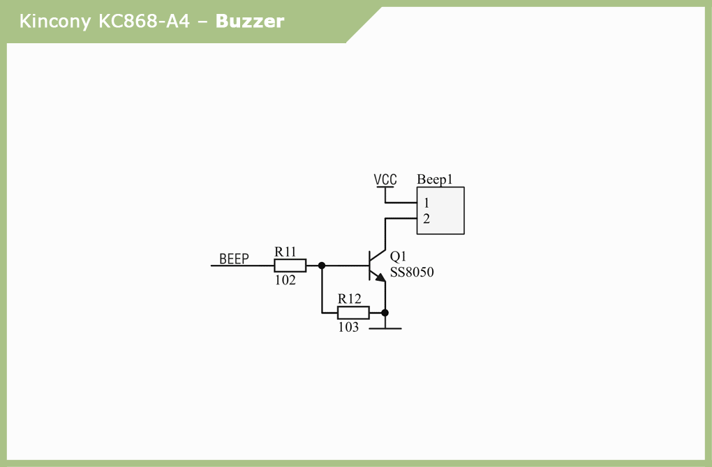
▍ Buzzer
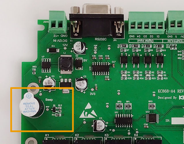
The scheme of the piezoelectric emitter is extremely simple and does not need comments, I will only note that the very presence of the squeaker is very useful, since it is possible to easily and regularly notify users of various events.
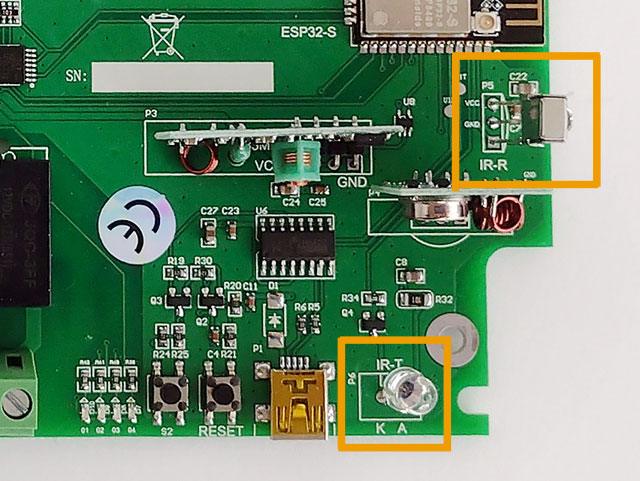
▍ Infrared reception/transmitter
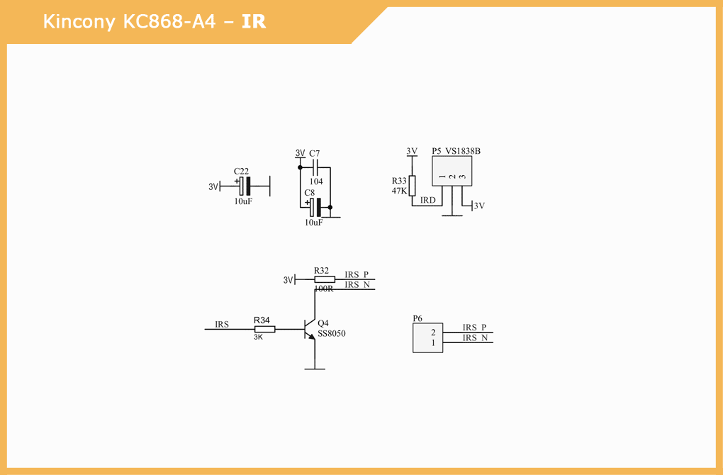
The Kincony KC868-A4 is equipped with an infrared receiver and emitter. As an IR receiver, the VS1838B sensor with the appropriate strapping is used. The official documentation of the KC868-A4 contains an error in the connection scheme of the emitting IR diode – the P6 pad there is drawn six-pin, in fact, the diode is connected, as it should be, using two pins. Below is the already corrected diagram.Schematic diagram of the subsystem of the infrared receiver and transmitter:
▍ 433 MHz modules
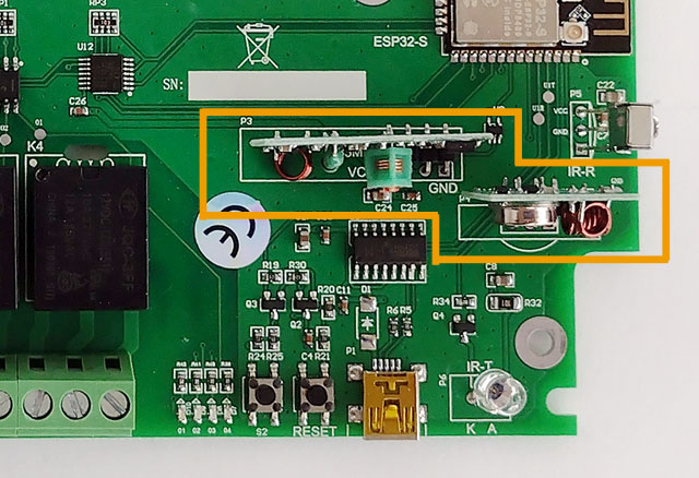
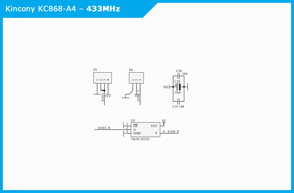
Initially, the Kincony KC868-A4 board comes with empty connectors for connecting the receiver and transmitter at 433 MHz. As wireless, popular modules at 433 MHz are used, which you can buy yourself on Aliexpress. In the case of buying a full controller, Kincony itself seals these modules in empty connectors.To form and supply the controller with an input signal from a 433 MHz receiver, a 74LVC1G125 buffer element is used, and the output signal to the 433 MHz transmitter is supplied directly.Do not forget that the modules are supplied without antennas and for their normal operation you need to solder a piece of wire 17 cm (quarter wave) to them.Schematic diagram of the wireless connection subsystem 433 MHz modules:
▍ RS232 port
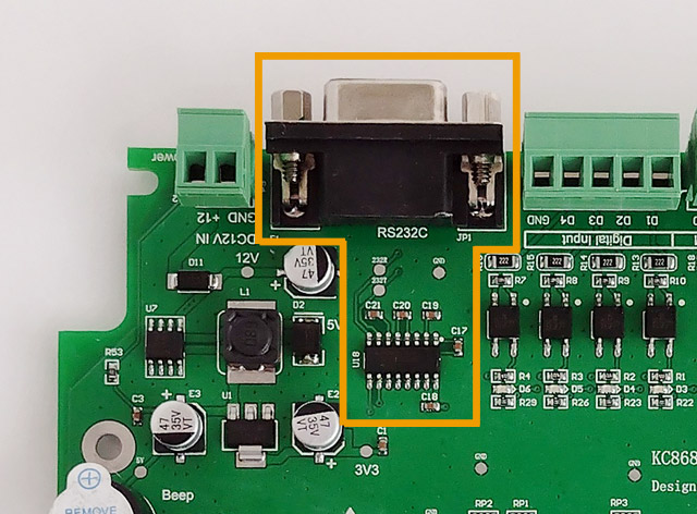
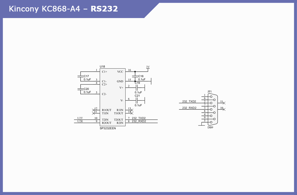
Kincony KC868-A4 is equipped with a full-size DB9 port for connecting devices to it via RS232. Signal generation is handled by interface converter SP3232EEN.Circuit diagram of the RS232 port subsystem:
Conclusion
In this article, I gave a general description of the Kincony KC868-A4 controller and analyzed its circuitry and device. In the next article, we will take a closer look at the ESP32 pinout and analyze the connection of the KC868-A4 function blocks and their programming.
