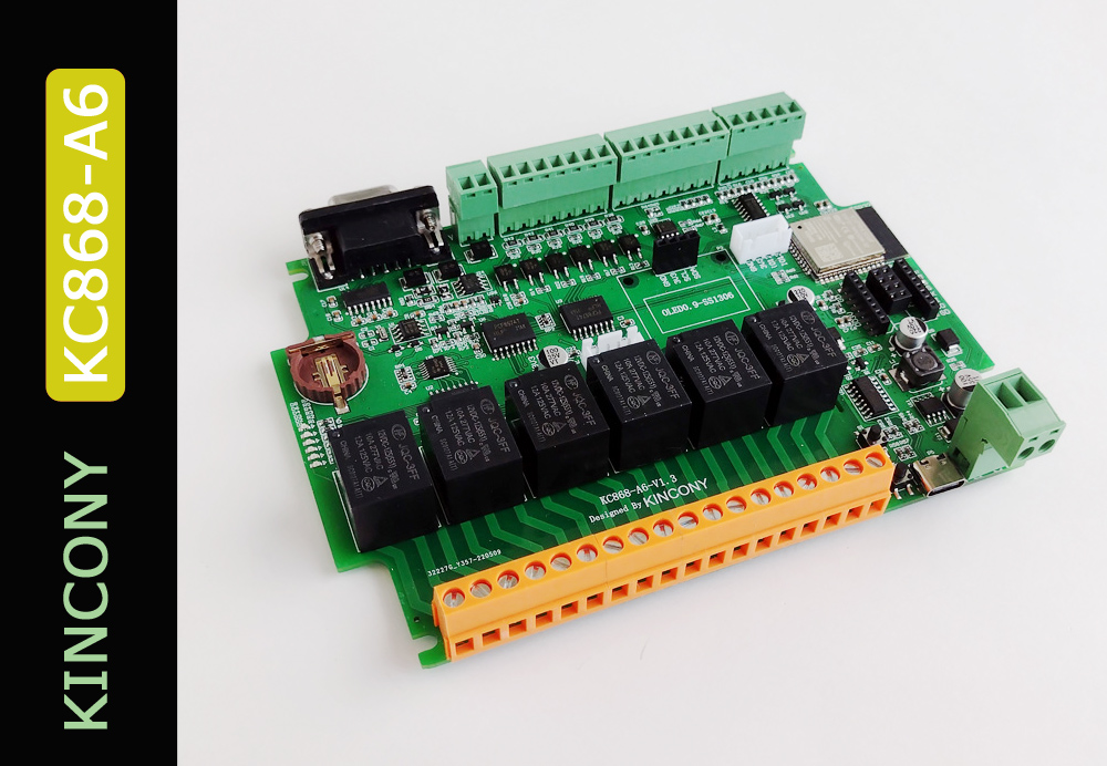
Kincony is distinguished by its enviable skill, developing new controllers like Lego bricks – a new model every month. They are obviously not tired. That would be called:
“Continuity of development and the ability to recognize new trends.”
That is, they will continue to please us with their new automation devices. This is great news, but there is even better news: Kincony is responsive to customer requests to improve their products and develop new ones. This practice is rarely found in other manufacturers. Kincony developers are familiar with the requirements and needs of adding a display controller, the ability to connect LoRa and nRF24 wireless modules, on-board connections of separate Serial, I2C and SPI connectors, adding a real-time clock (RTC) – and here in front of me lies the KC868-A6, in which all these desires are present. Of course, this is not the end of development, there are a number of new ideas that will be realized in the next controller models…
Kincony KC868-A6
The KC868-A6 gives the impression of the “KC868-A4 on steroids” – all the same, but a little better, a little larger and “stronger” – more digital inputs and relays, more inputs for sensors, a display was added, the ability to connect wireless nRF24 and LoRa modules, separate connectors Serial, I2C and SPI interfaces, a real-time clock (RTC) and RS485 interface.
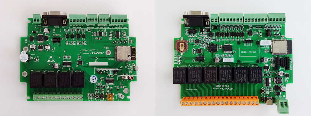
A4 and A6 for comparison
Absences such as a piezo-ceramic buzzer, an IR diode and a 433 MHz module can be considered insignificant, although I personally feel sorry for the buzzer – it is convenient to inform about various alarm conditions with it. Despite significant steps in the right direction, the KC868-A6 still does not reach the honorary title of “All-in-one controller of our dreams” – Kincony engineers traditionally ignore the need for a hardware Watchdog function on the A6 controller. Maybe one day I will be able to reach out to the developers and convey this good idea to them. As usual for the KC868 series, this is an ESP32 module in the ESP-WROOM-32 modification with all its built-in capabilities (Wi-Fi, Bluetooth, two MCU cores, 4 MB EEPROM memory, etc.). In addition, the KC868-A6 features:
- 6 digital optocooled inputs (“dry contact”)
- 4 analog inputs 0-5 V
- 2 analog outputs (DAC) 0–10 V
- 6 relays 10A 220V (NO, COM, NC)
- 2 contacts for connecting temperature and other sensors
- Serial Connector
- I2C connector
- nRF24L01 Connector (SPI)
- LoRa Connector (SPI)
- RS232 interface (DB9)
- RS485 interface
- Display (SSD1306)
- RTC DS1307 (+ battery socket CR1220)
A little more detail on what all this means and what it gives us:
Serial Connector. The ability to connect various equipment (components) operating on this protocol, as well as the ability to connect a “partner” MCU.
I2C connector. Same as Serial.
Connector nRF24L01. The ability to integrate into the system dozens (if not hundreds) of wireless DIY sensors, actuators, indicators, etc. As well as the ability to use this connector to connect SPI components (instead of nRF24L01).
In more detail: if there is nRF24 on board the controller, then the KC868-A6, for example, no longer supports 6 relays, but can support the operation of dozens (hundreds) of wireless relays. Which brings the controller itself and its capabilities to a completely different level.
And even more: with the appropriate software support (packet delivery control, re-sending, encryption, etc.), wireless nRF24 (as well as LoRa) connections can be almost as reliable as wired ones.
LoRa connector. Same as nRF24, plus the whole complex of possibilities associated with LoRa-specifics: long communication distances, etc.
RS485 interface. No comment.
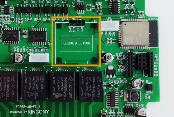
Display. As I noted earlier in one of the articles, “a controller with a display is much more interesting than the same controller, but without a display.” Further, it remains only for your design and construction abilities (to decide what, when and how to output to it).
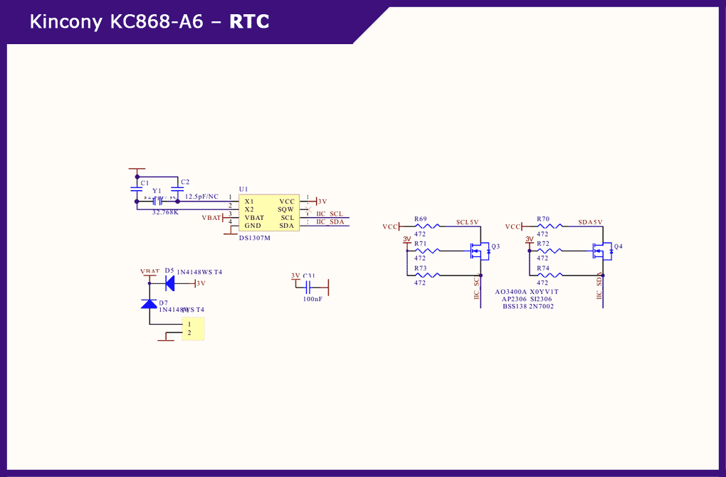
RTC DS1307. The long-awaited RTC on board (who did real projects, he will be able to appreciate its presence). True, the implementation was a little disappointing, but we will talk about this in detail a little below.
ESP32. About ESP32 and its (web)interface and communication capabilities, I do not even mention – we have discussed all this in detail in previous articles. In general, the KC868-A6 in the right hands is a terrible weapon of DIY automation (the main thing is that the hands are skillful enough). And now we move on to getting acquainted with the appearance and device of the KC868-A6.
Appearance and device
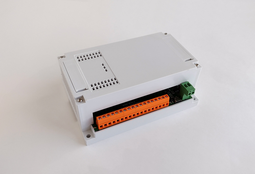
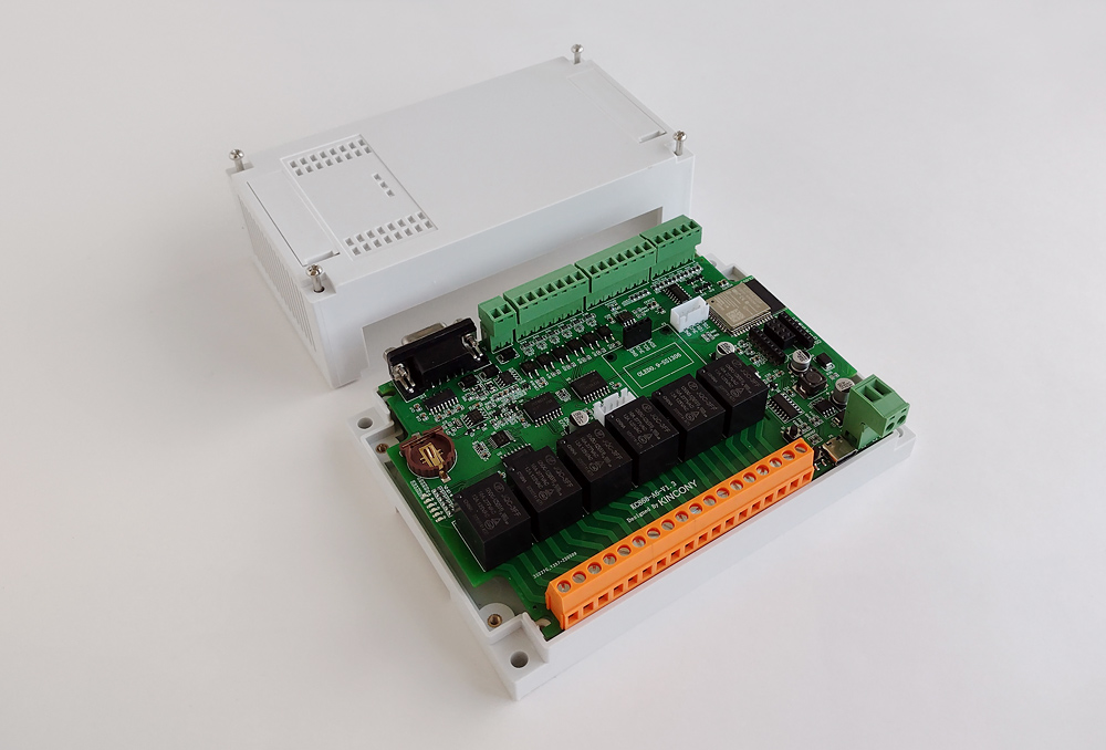
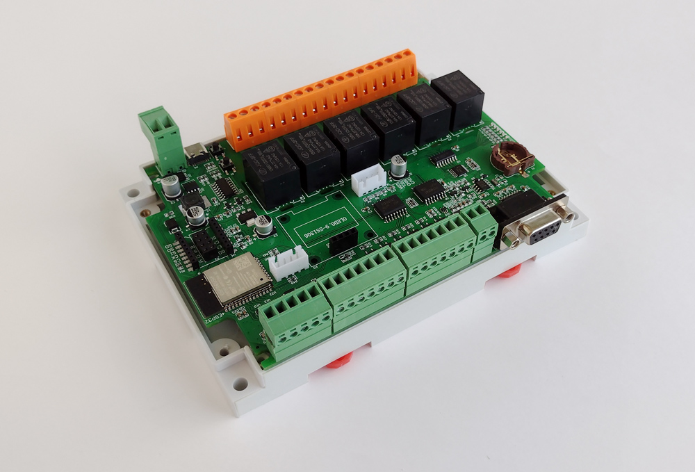
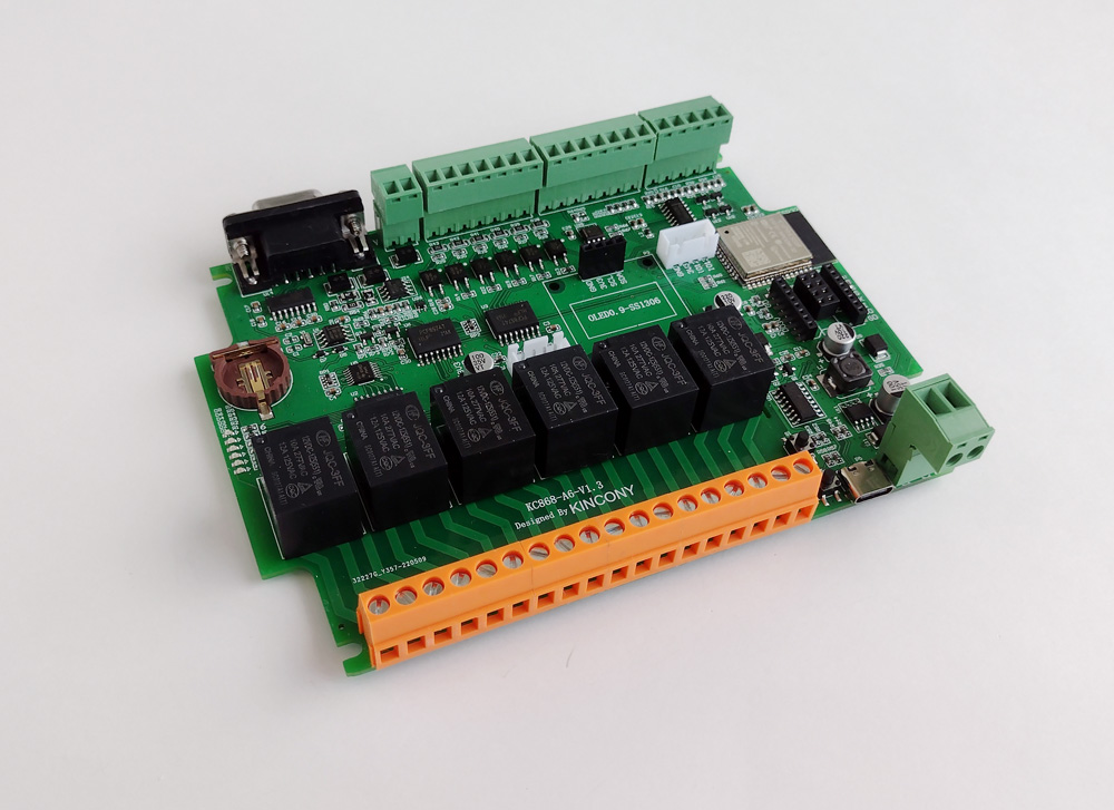
As they say, “modestly, but tastefully”, the appearance of the Kincony KC868-A6 does not stand out, but the controller looks quite nice and functional. I personally like the case both from the point of view of design and from the point of view of functionality: plugs for external connectors, a place for the display, convenient fasteners and ease of disassembly, high-quality plastic, metal fasteners for bolts and ventilation holes, the possibility of installing on a DIN rail or any surface – everything is very, very good, if not to say “good and excellent”. However, in the comments to previous articles, someone expressed an opinion, that the case has a non-standard geometry and this is bad, but according to the totality of the advantages, I would turn a blind eye to its “non-standard” shape. The view of the controller with the lid removed – inside we observe the same approach to the design of Kincony devices: everything is done neatly and functionally. Especially pleased with the presence of free space in the case – you can safely place an additional board with the necessary components, attaching it to the top cover and connecting it to the main board with cables. The type of the KC868-A6 board in the “pallet” of the case on the reverse side – you can see the connectors of digital and analog inputs, DAC, RS232 and RS485 interfaces, as well as mounting plates for fixing the controller on the DIN-rail. The KC868-A6 board itself. You can not use the complete case, but fix it with the help of special holes (recesses) on any suitable surface or inside your DIY device for automating something.
Circuit technology
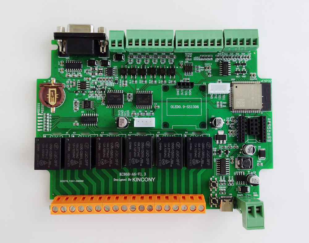
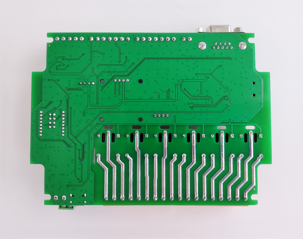
Now let’s move on to a closer acquaintance with the KC868-A6 and the analysis of the circuitry of this controller. First, a view from above. Immediately catch the eye of numerous additions and improvements, compared to the A4. The view of the board from below. There is nothing much to comment on, everything is visible in the palm of your hand. However, having become closely acquainted with the model range of controllers of the KC868 series, I can notice that some models go clean, with a well-washed, and some contain residues of poorly washed. The A6 is one of the latter – before shooting the back of the board, I had to manually wash it from the remnants of the flux.
Power supply
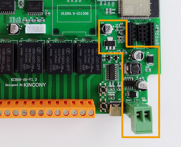
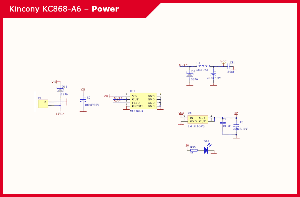
Standard for the KC868 series power subsystem: uses a chip step-down DC-DC converter XL1509-5 to form voltages of 12 V and 5 V and a linear regulator LM117-3V3 to generate a voltage of 3.3 V. The pad for connecting power wires has moved from the top side of the board to the bottom – Kincony demonstrates the ease of manipulating the location of elements on the board and the design of connectors for connecting equipment to the controller. Power Supply KC868-A6:
ESP32 Core
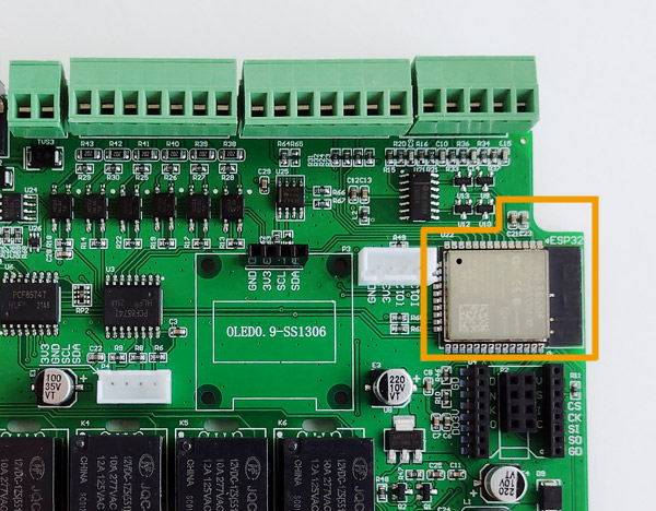
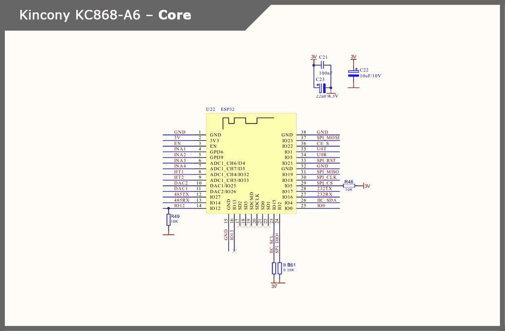
Here everything is simple – the standard, which has already become classic for the KC868 series, the location of the ESP-WROOM-32 module on the board. Plus the filter capacitors for power, located near ESP32. The antenna of the Wi-Fi module is located close to the antenna nRF24L01 (when using it) – here you need to make sure that they do not interfere with each other during operation, since both modules operate in the range of 2.4 GHz. Schematic diagram and pinout of the ESP32 core of the controller:
USB/CH340
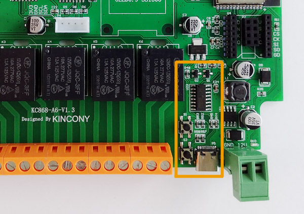
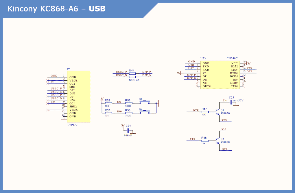
Subsystem for connecting to the computer and programming the controller. The Mini-USB connector has been replaced by a more modern Type-C, followed by the CH340C with the appropriate strapping and two buttons – “RESET” and “USER” (“DOWNLOAD”). Schematic diagram of the USB/CH340 subsystem of the controller:
Digital Inputs (DI)
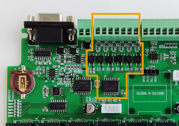
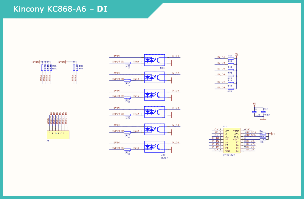
6 inputs is definitely better than 4 on the KC868-A4. The KC868-A6 has 6 digital opto-isolated inputs on the EL357 optocouplers. Interaction with ESP32 is engaged in the extension of digital inputs / outputs with I2C interface PCF8574P, which saves scarce GPIO, although it worsens the performance of inputs KC868-A6 and somewhat complicates programming.
Analog Inputs (ADC)
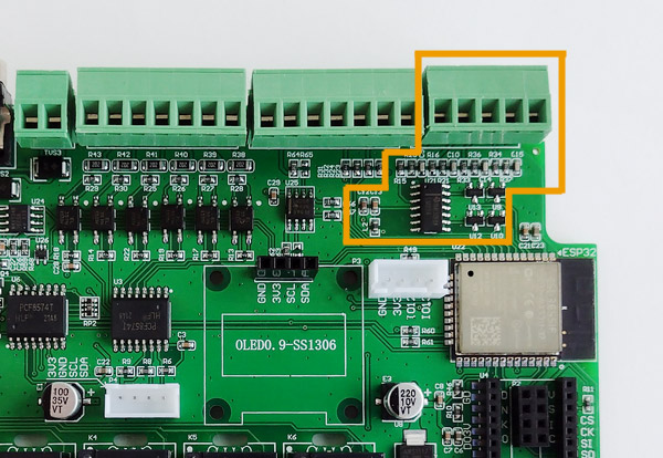
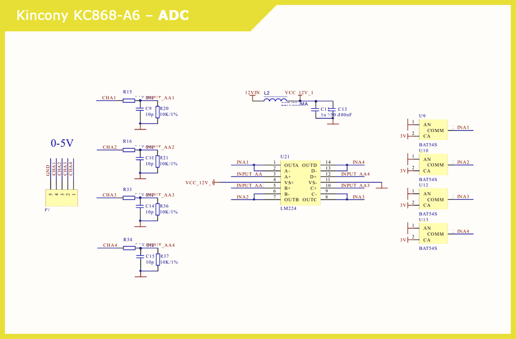
KC868-A6 has 4 analog inputs 0-5V. Signals are formed by input stages, a quadruple LM224 operational amplifier and Schottky DIODEs BAT54S. Immediately the voltage of the VCC_12V_1 is formed. Schematic diagram of the analog input subsystem:
DAC
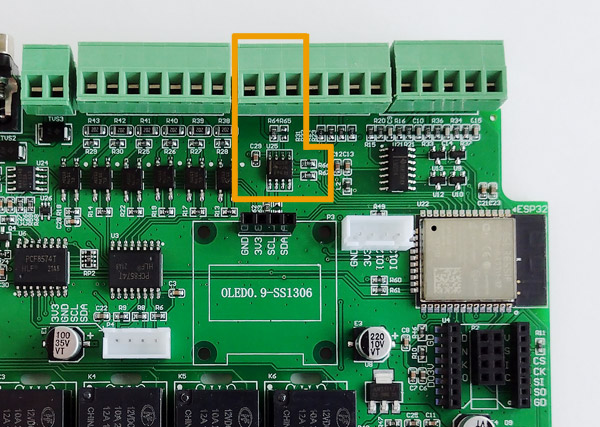
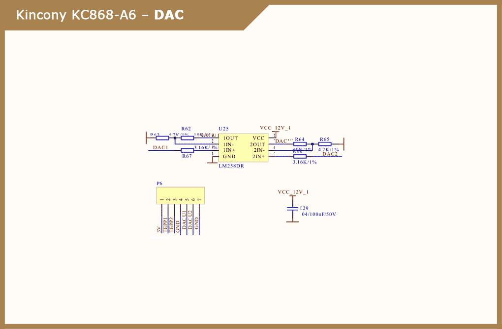
The formation of analog output signals 0-10 V is carried out by a dual operational amplifier LM258DR with the appropriate strapping and powered by 12V_1 / AGND. In pad P6, the DAC outputs are aligned with the sensor inputs (temperature, etc.). Schematic diagram of DAC controller subsystem:
Relay’s
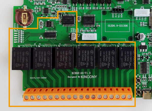
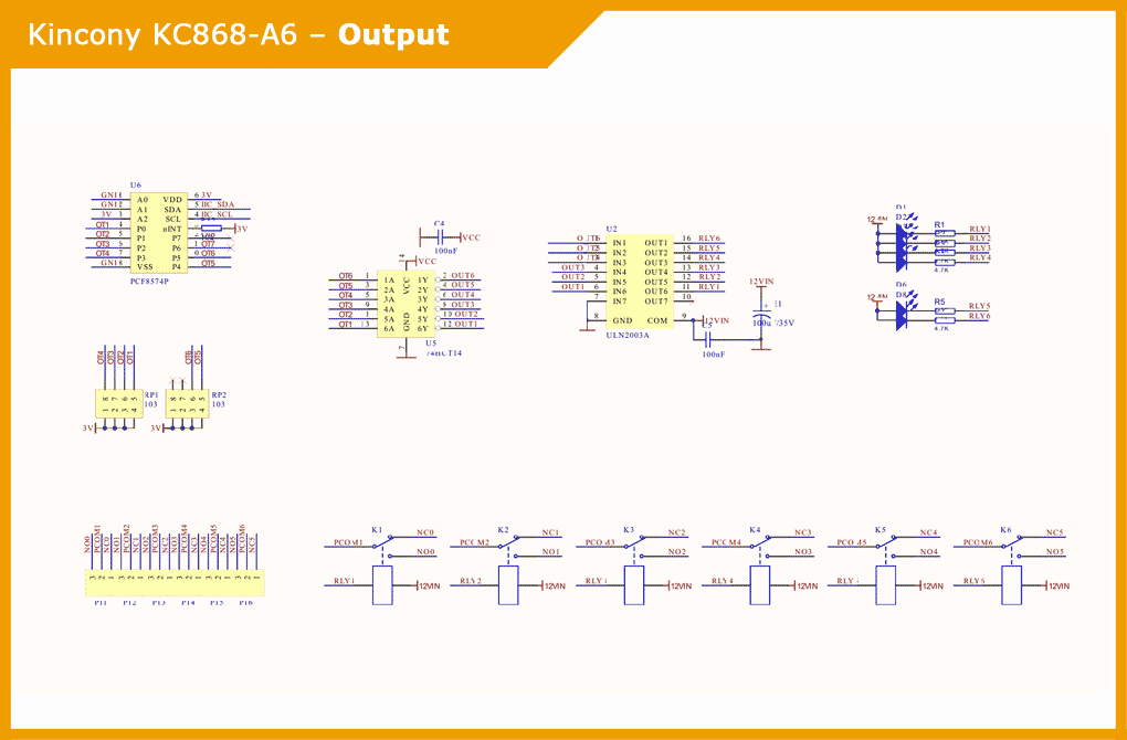
The relay subsystem occupies half of the Kincony KC868-A6 controller. Maintenance of the 6 relay is carried out by the chip 74HCT14 with inverting Schmitt triggers and ULN2003A with Darlington transistor arrays. On the board there are indicator LEDs that signal the current state of the relay. Interaction with the microcontroller ESP32 is carried out using the digital input/output extender with I2C interface PCF8574P.Relay outputs have all 3 contacts (NO, COM, NC), which allows them to be fully used in various power on/off load circuits. Also in this version of the controller, the relay pads are replaced with more powerful ones, compared to the KC868-A4 pads. Schematic diagram of the relay subsystem:
Sensors (temperature/humidity)
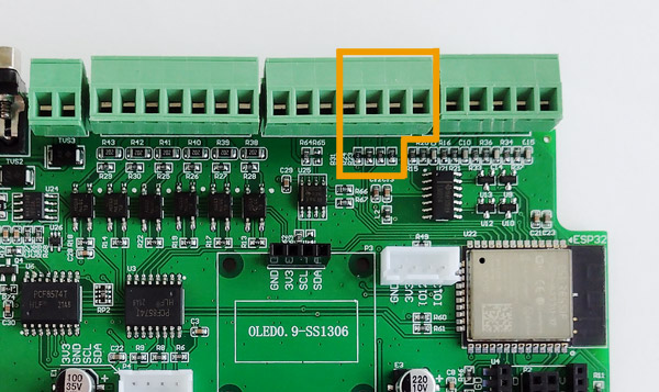
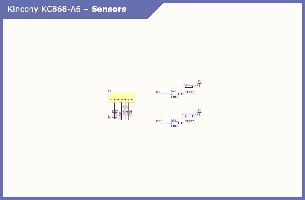
KC868-A6 has 2 connectors for connecting temperature and other sensors (you can connect any suitable sensors or networks of several sensors, you just need to remember that all contacts on the board are tightened to a voltage of 3 V). In extreme cases, you can remove the tightening resistors from the board and get “pure” GPIO, to which you can connect the equipment you need.
Serial
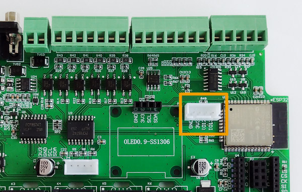
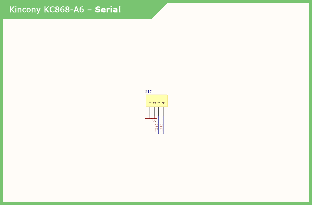
Separate Serial connector (GPIO12, 13) for connecting the appropriate equipment (any components operating on this protocol or “partner” MCU). Separate connectors with different interfaces on the board – this is always good and can only welcome the appearance of a separate Serial connector at the KC868-A6.
RS232
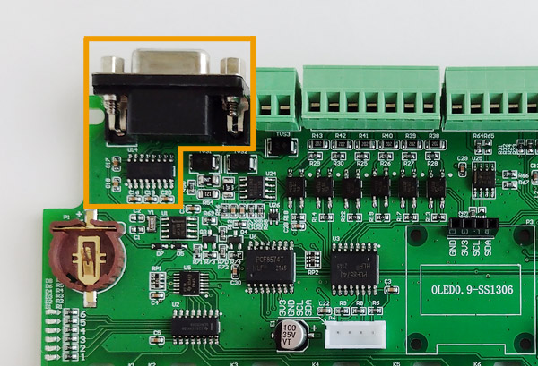
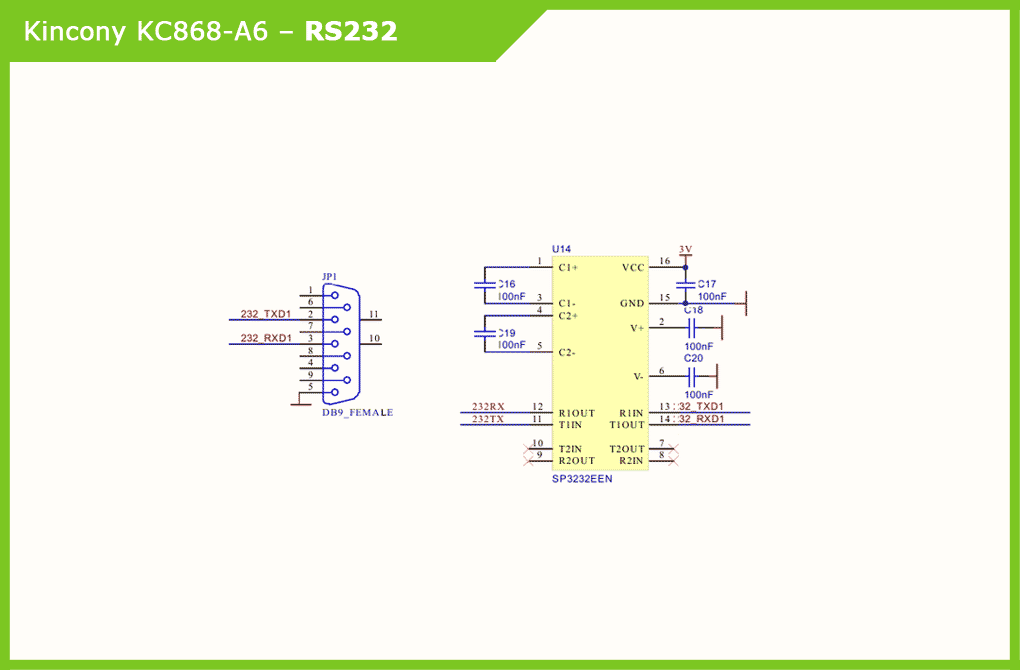
Despite the presence of the RS485 port, Kincony designers also installed a DB9 connector port RS232. Apparently, the popularity of connecting equipment via the RS232 port is still high. Schematic diagram of the RS232 subsystem:
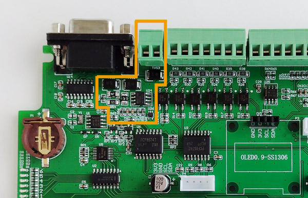
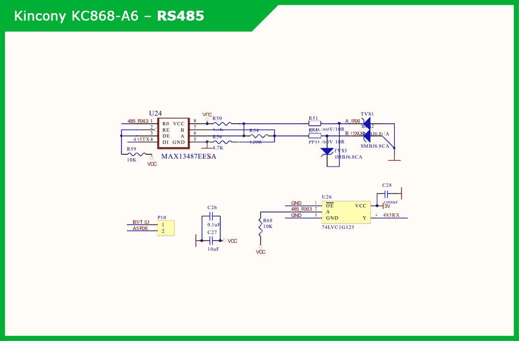
RS485
The lack of RS485 port support on some earlier KC868 controllers has been resolved with this version.
This subsystem provides the MAX13487EESA driver and interface buffer and the 74LVC1G125 buffer. Schematic diagram of the RS485 interface subsystem:
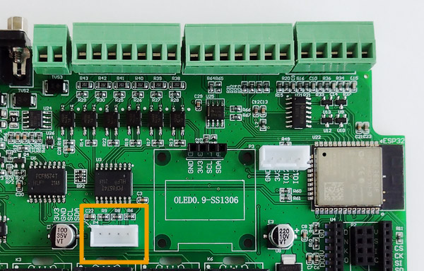
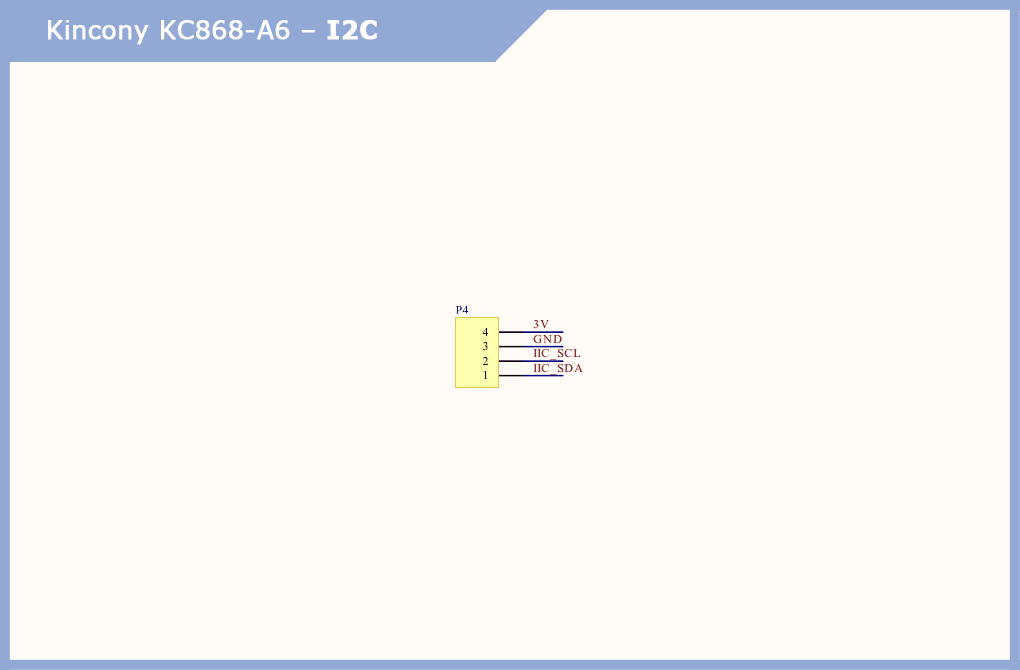
I2C
As I noted above, separate connectors with interfaces on the board are always a good thing. A separate I2C connector is just fine: you can connect any additional I2C-compatible components to it and significantly expand the functionality of the controller.
Wireless (nRF24 and LoRa)
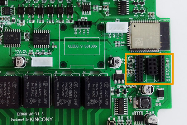
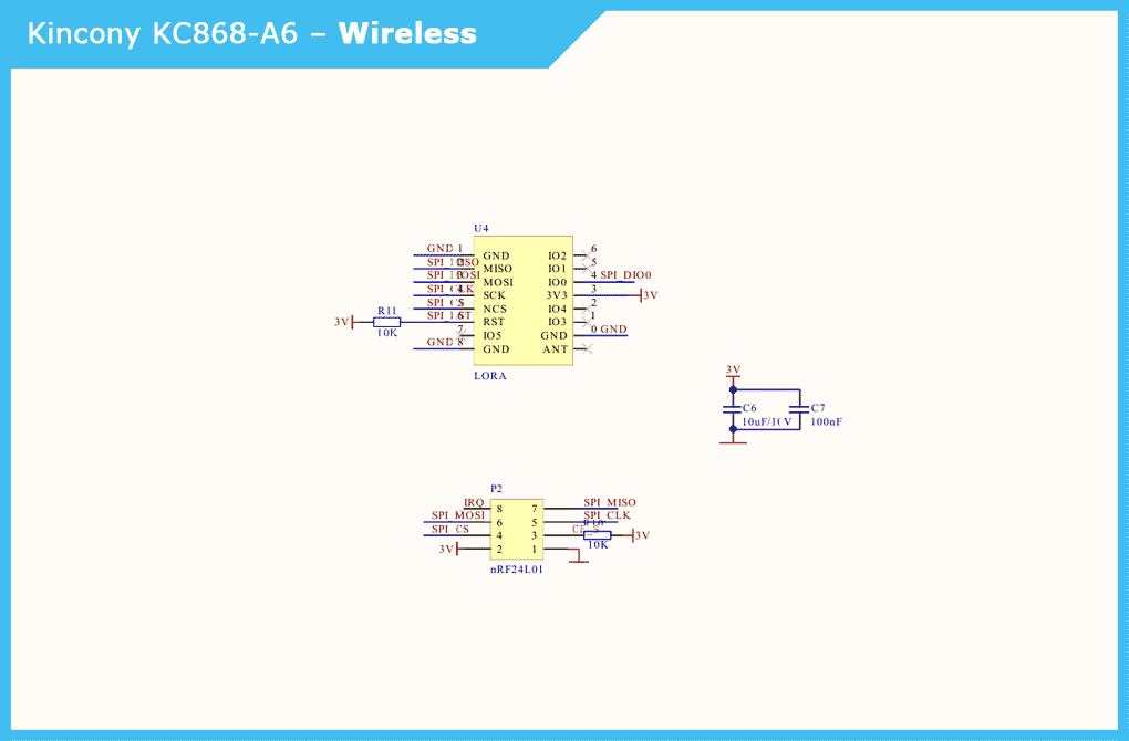
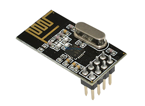
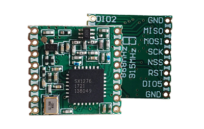
In my opinion, the main “feature” of the KC868-A6 is the ability to connect nRF24 and LoRa modules. This significantly expands the functionality of the controller – it becomes possible to control dozens and hundreds of wireless sensors and actuators. As you can see, it is impossible to use both nRF24 and LoRa at the same time, they can only be used separately. That is, you must choose to use a particular wireless network. On the other hand, if you really need, you can try to insert one module into the appropriate connector, and connect the second with wires (cable) – what will come of it and how it will work you need to check separately, I have not yet conducted such experiments. Instead of wireless nRF24 and LoRa modules (if by design you need to connect some equipment with SPI interface to the controller). Schematic diagram of connecting wireless nRF24 and LoRa modules (SPI interface). Popular and beloved module nRF24L01, which is (successfully) used in thousands of DIY projects. No less popular and no less beloved LoRa module, which is also successfully used in many DIY projects. And now you can connect these wonderful modules to KC868-A6 and make it the master of your wireless IoT network.
Display (SSD1306)
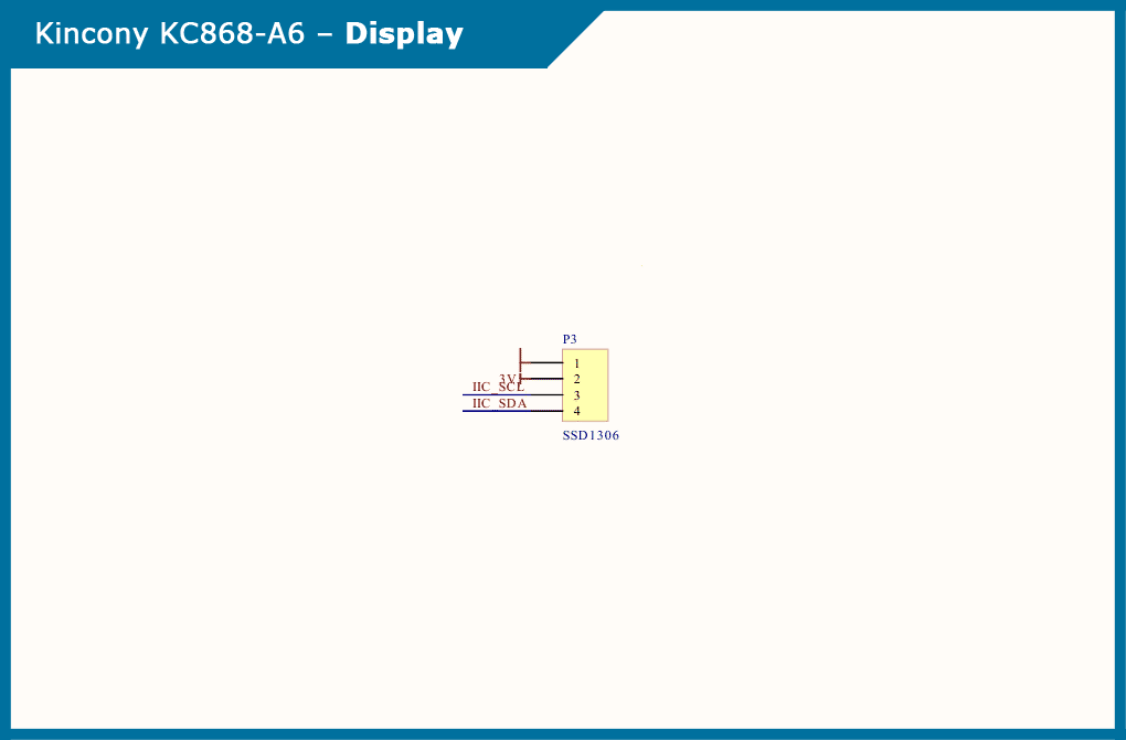
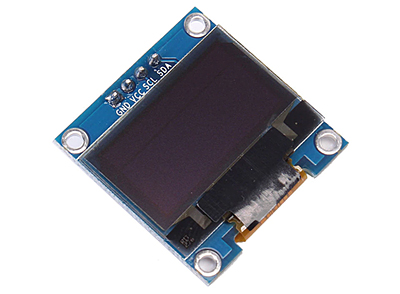
The display is what Kincony controllers have been missing so much, and you can now connect the popular SSD1306 display to the KC868-A6 and output all the information you need to it. By the way, it is not necessary to use SSD1306, you can connect any display with I2C interface. For example, some display with a larger screen than the SSD1306. And you can also use the display connector to connect other I2C equipment if the display is not needed in your project. Schematic diagram of the display connection: The I2C display itself SSD1306.
Also popular and used in many DIY projects. Affordable, inexpensive and supported in the form of libraries.
RTC
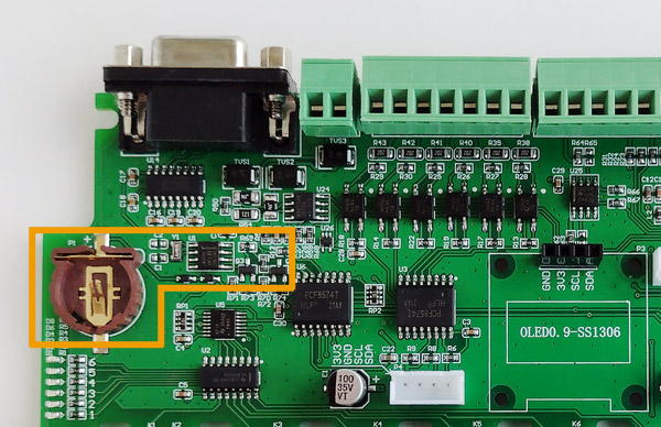
Another highlight of the KC868-A6 is the RTC (Real Time Clock). Finally, Kincony added this subsystem to its board. I will not talk about the importance of RTC in real projects, I will just note that in many cases it is an extremely useful and even necessary function. Among the shortcomings of the implementation, we can note the use of the DS1307 chip, which is known for its inaccuracy and large deviations of the time from the real value. This limits the use of this solution, although such an RTC is still better than none. This problem can also be easily solved by downloading the correct time from many weather servers. However, Kincony promised to fix the above and in the next revisions of the board to put a normal RTC chip DS3231 with an accurate countdown. Both chips are software compatible, so the transition to the new board will be painless.
Schematic diagram of the real-time clock subsystem:
Pinout
Next, here is a pinout that gives a comprehensive idea of what and how is connected on the KC868-A6 controller board.
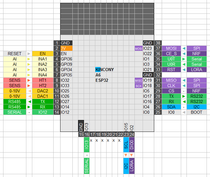
Diagram of external connections
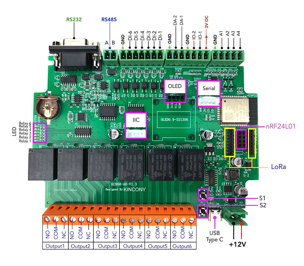
And, by tradition, I give a slightly cultivated scheme of external connections from the manufacturer.
Conclusion
After reading this article, you should know the purpose and characteristics of the KC868-A6 controller
should have been clearer and more understandable. The controller is ideal for studying, experimenting and performing real IoT projects and automation processes.
The easiest way to create a program is through the Arduino development environment.
The KC868-A6 proved to be reliable and easy to use.
