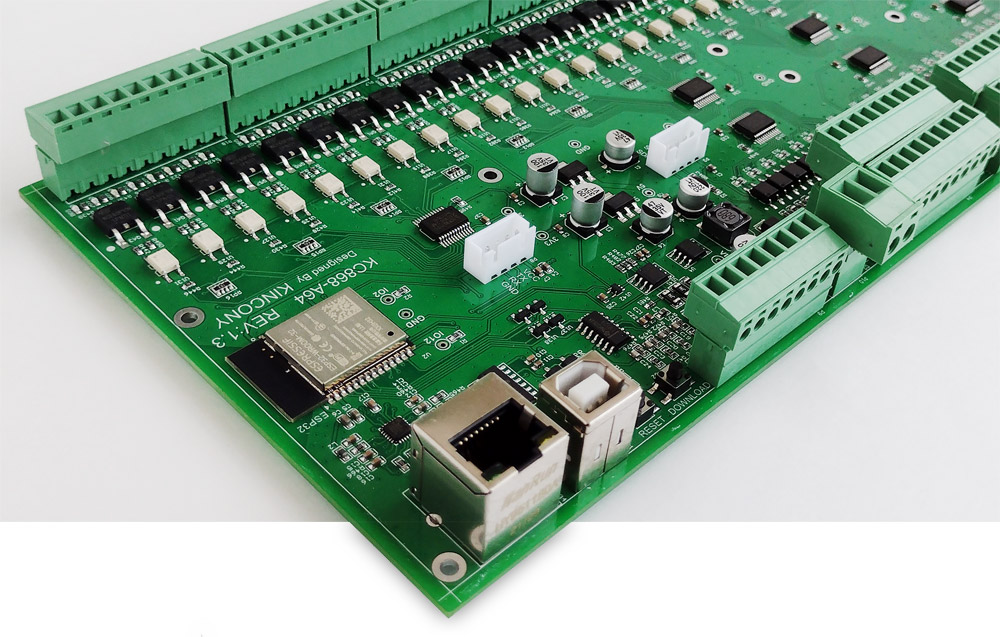
It seems that many Kincony controllers are quite a bit but powerful and incredible size, with a large number of digital inputs and outputs, many interfaces, etc., but this is only done to you at first glance, until you need, for example, to receive information from 64 digital inputs and control 64 valves or relays. Today we will meet the controller, Kincony KC868-A64, which occupies an honorable place in the line A4, A6, A8, A16, A32, A64 and allows you to solve complex and high volume the tasks of automation.
Features of the KC868 line
According to the type of output management control, the KC868 series controllers are divided into two categories: devices with relays installed on the board (A4, A6, A8, A16S, A32) and devices with transistor outputs (MOSFET) (A16, A64, KC868-Server). Controllers with relays are additionally divided into devices with fixed – soldered relays and devices with relays built into special “bases” that allow us to replace burned relays quickly and without soldering. Each of these options has its advantages and disadvantages. Controllers with relays are easier to use, it does not have to be used with anything additional buy and additionally connect, while controllers with transistor outputs can, but not necessarily drive operate devices or it must be solved through external relays or contactors. In this case, it is necessary to additionally purchase and install separate relay units, for example, unit KC868-E16 or similar.
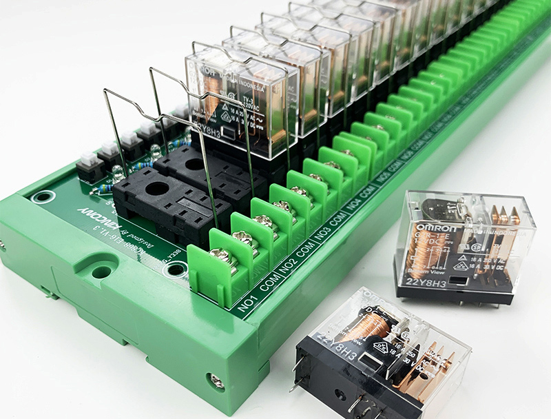
The additional relay unit KC868-E16
KC868-A64 belongs to another type, if your project requires the use of relays, you will need to additionally purchase and connect the appropriate units from Kincony or similar third-party manufacturers.
Kincony KC868-A64
The Kincony KC868-A64 controller contains many installed components and subsystems, the full list of which is below:
- ESP32 (ESP-WROOM-32)
- 64 digital opto-insulated inputs (“dry contact”)
- 2 analog voltage inputs 0-5 V
- 2 analogue current inputs 4-20 mA
- 64 MOSFET outputs 12/24 V for relays and other control equipment’s
- 64 LEDs for output status
- The ability to connect multiple units KC868-E16 or the equivalent’s
- RS485 interface
- Two separate I2C connectors
- Separate serial port
- Ethernet LAN8270A
- USB port for programming and upload firmware
- Restore and Download buttons
- Powered by 12/24 V DC
In other words, we have wireless Wi-Fi and wired Ethernet at our disposal, sensing 64 inputs (+ 4 analogues), we manage 64 MOSFET output and also exchange data via RS485. Additional equipment’s can be very diverse and significantly expand the basic functionality of the controller (for example, display, various sensors, communication modules, etc.). As a result, on the basis of KC868-A64 it is possible to build very complex IoT systems, the main “chip” will has the ability to receive data from 64 digital inputs and manage 64 MOSFET digital outputs.
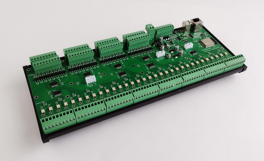
KC868-A64 assembled, ready to mount ma DIN rail
Layout and construction
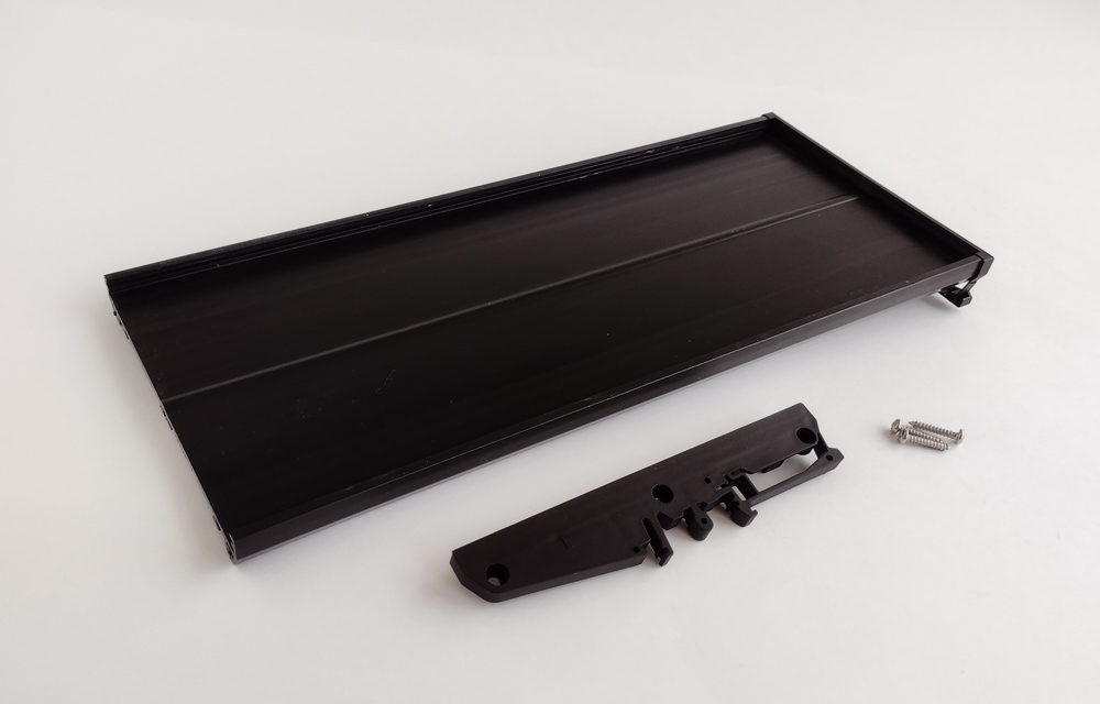
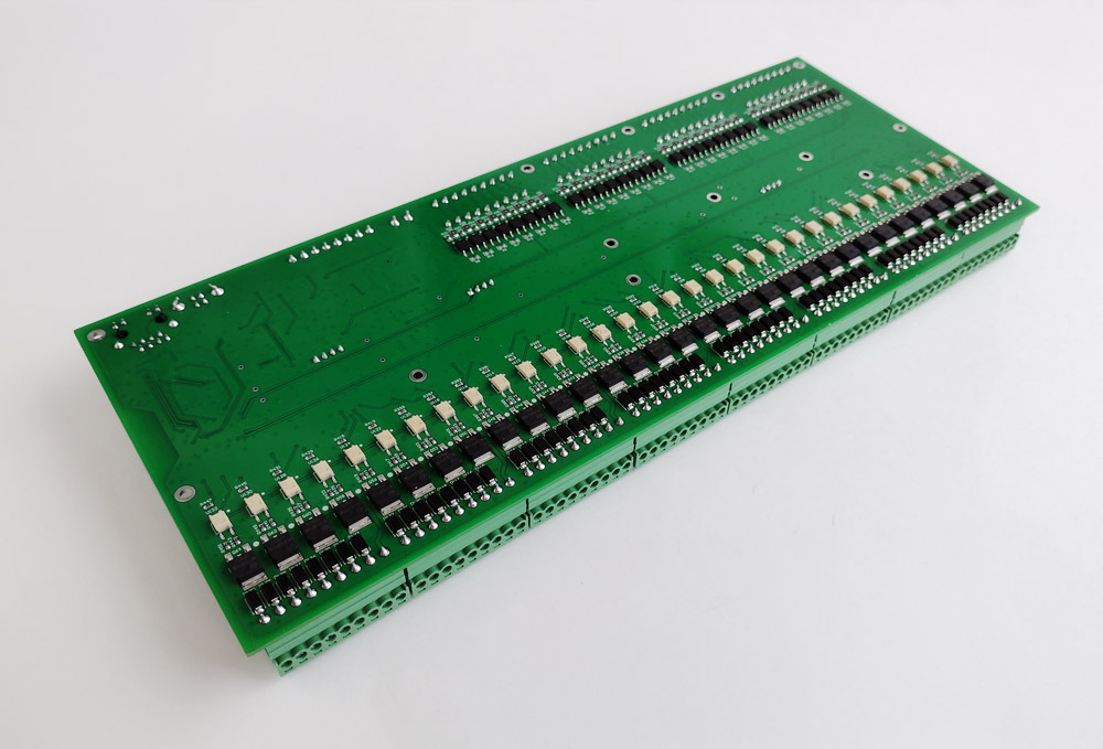
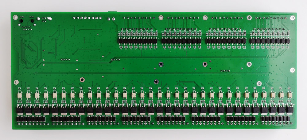
Due to its large size, the KC868-A64 will not fit in any standard housing, so it is equipped with a special profile for installation and assembly on the DIN rail. Everything can be assembly and disassembly very simple – just unscrew a few screws along the edges of this profile. The controller itself is inserted into the profile on the side, and then simply fixed with side stoppers. Due to the large number of digital inputs and outputs, the back side of the panel contains optocoupler’s and MOSFETs, which is non typical for Kincony products – usually the reverse side of the panel does not contain elements. Special mounting holes are visible on the surface – the controller does not need to be mounted on the DIN rail.
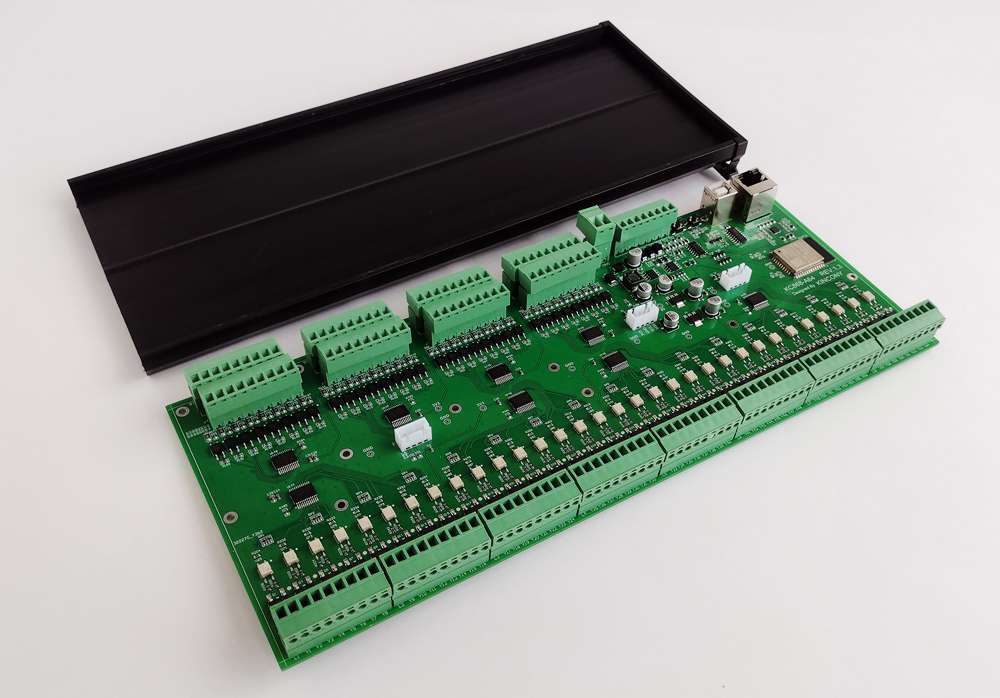
Subsystems on the board
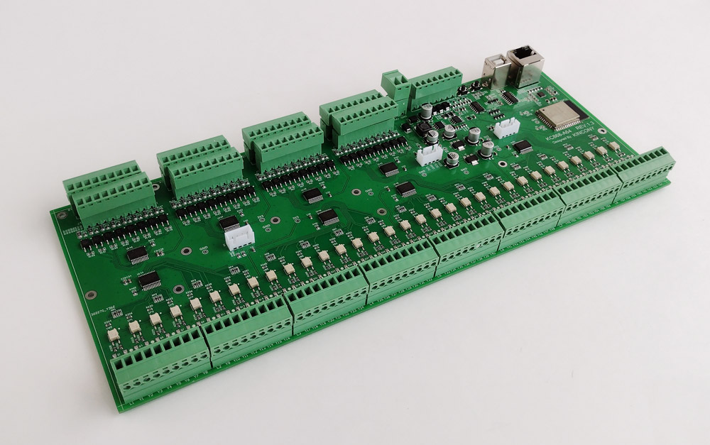
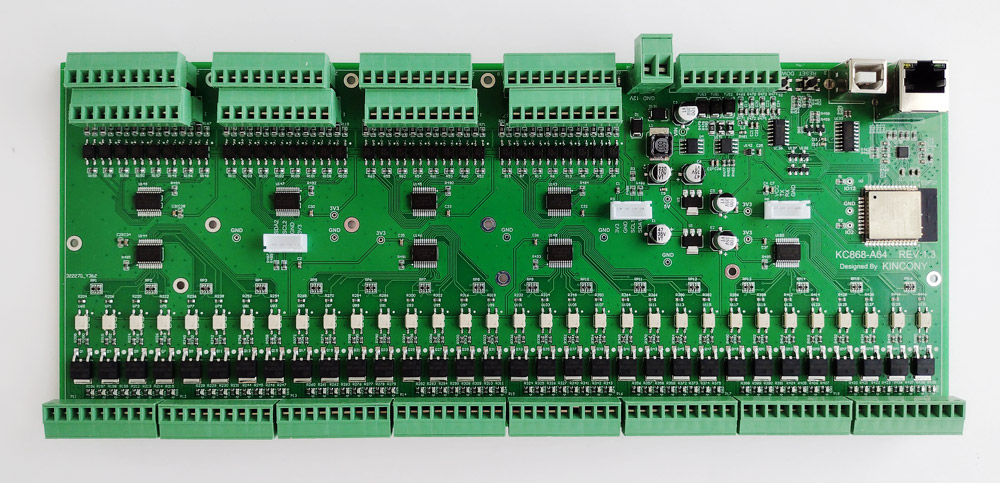
Let’s look at the KC868-A64 subsystems. First, look at the top side of the board. It’s all about the best traditions of Kincony and the KC868 series, it’s easy to recognize individual functional controller blocks.
A more detailed view of the underside of the board.
Power supply
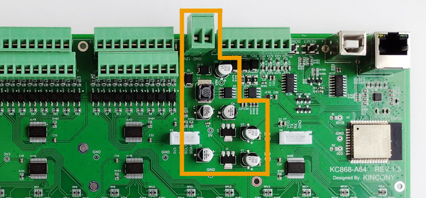
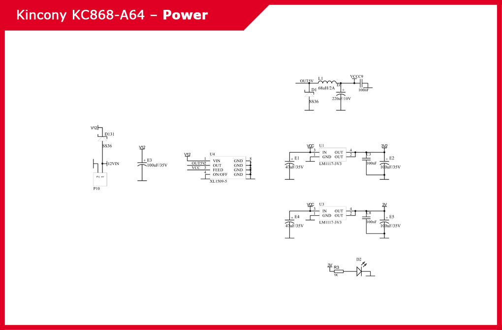
The KC868-A64 energy subsystem on the one hand is standard and repeats the typical solutions of other KC868 series controllers, but on the other hand it is some different from them. It also consists of a DC converter XL1509-5 for the voltage of 12V and 5V, but instead of one linear regulator LM117-3V3 for the voltage of 3.3V, two are used here.
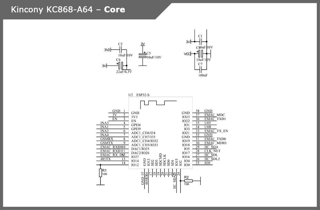
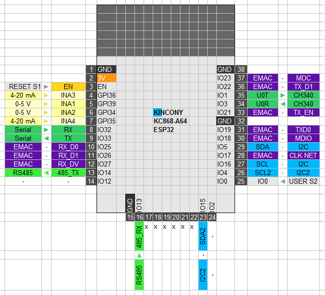
ESP32
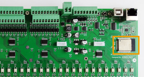
The core (processor) of the Kincony KC868-A64 controller is the famous ESP32 module (version of ESP-WROOM-32). The pin diagram is shown in the figure:
USB/CH340
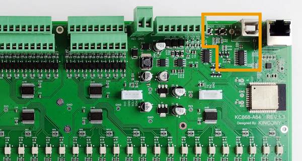
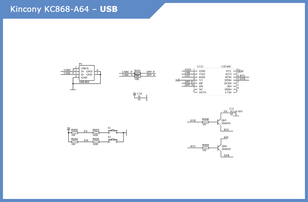
Standard USB-UART deployment on a CH340C chip plus vertical USB connector. There are also two buttons – “RESET” and “DOWNLOAD”. Schematic diagram of the USB/CH340 controller subsystem:
Digital inputs
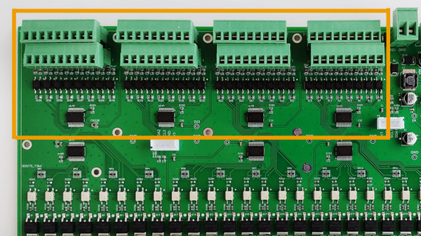
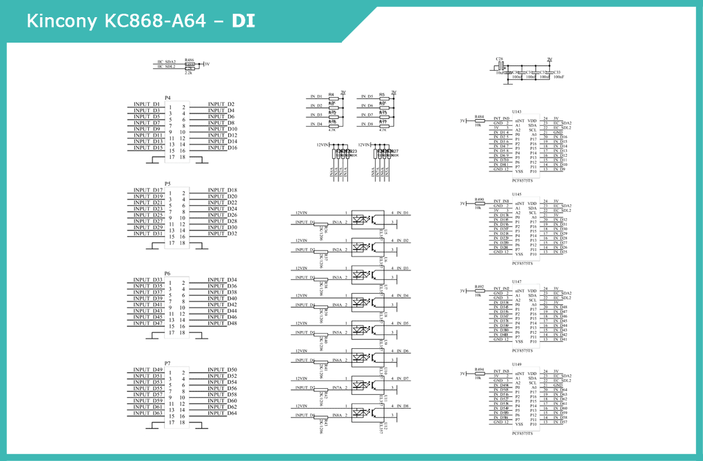
64 digital opto-insulated “dry contact” inputs on EL357 optocouplers, arranged in 8 connectors with 8 contacts each. To ensure their operation in cooperation with ESP32 in KC868-A64, digital input/output extenders with an I2C interface on 4 PCF8575TS chips were used. For clarity, the diagram shows only one of the eight blocks (the rest are completely similar to it).
Analog inputs
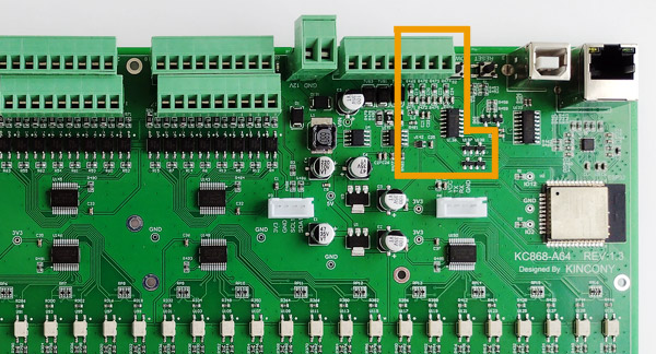
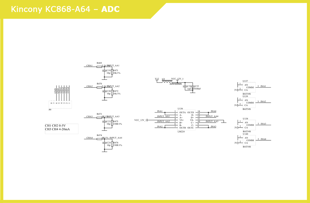
KC868-A64 has 2 analog voltage inputs for 0-5V signals and 2 current inputs for 4-20mA signals. Voltage generate quadruple operational amplifier LM324 and Schottky DIODE BAT54S. Immediately, the voltage of the VCC_12V_1 is formed. Schematic diagram of the analogue input subsystem:
MOSFET outputs
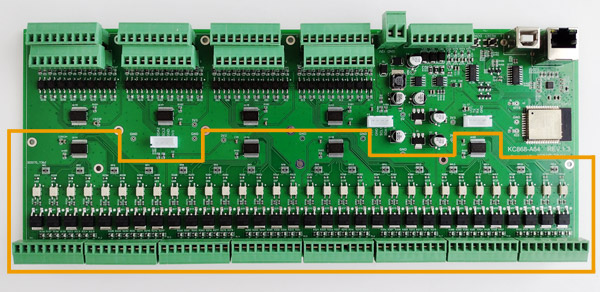
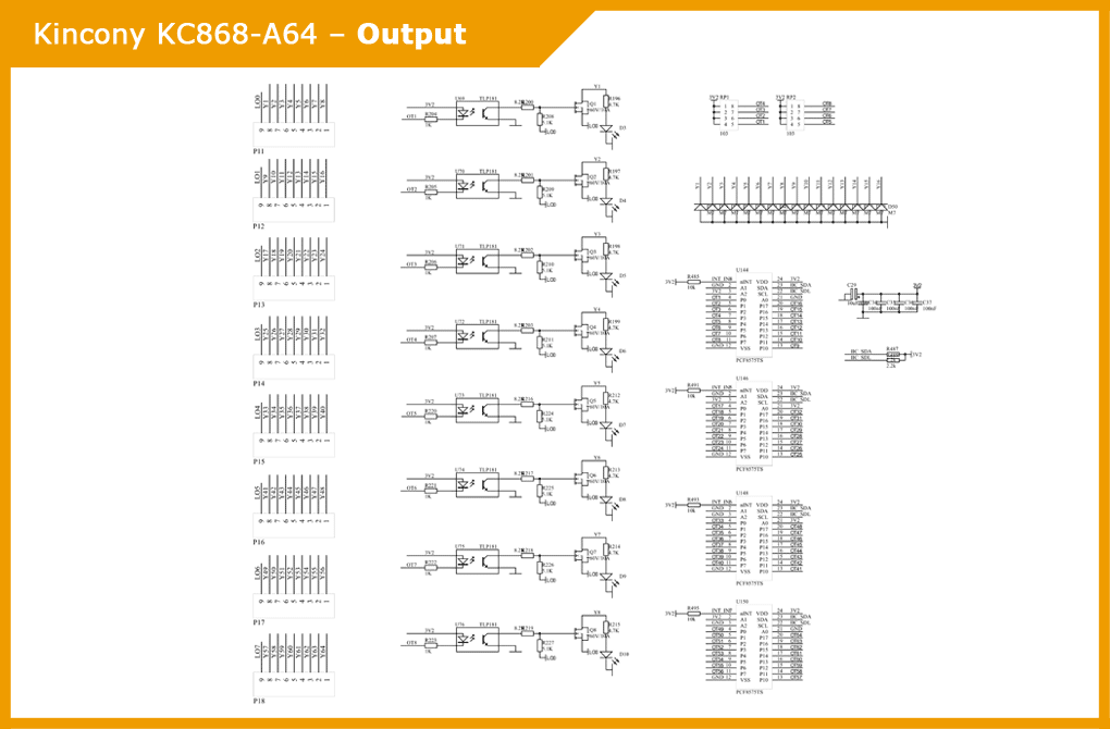
The largest subsystem of the KC868-A64 controller, the interaction of which with the ESP32 microcontroller is carried out using 4 digital I/O expanders with the I2C interface PCF8575TS. Control signals are received on TLP181 optocouplers, which control 64 MOSFET’s NCE60P10K. There are also indicator LEDs, which show the current state of output of the KC868-A64 controller.
Schematic diagram of the output subsystem MOSFET. For clarity, the diagram shows only one of the eight MOSFET blocks (the rest are completely similar to it).
Ethernet
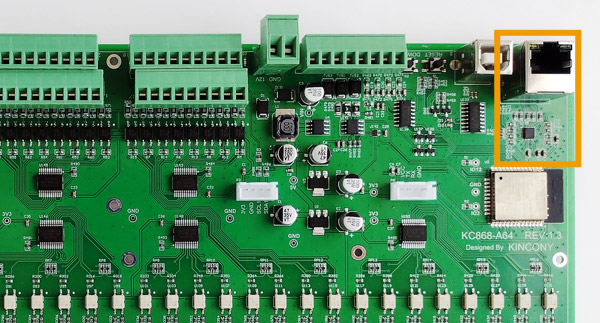
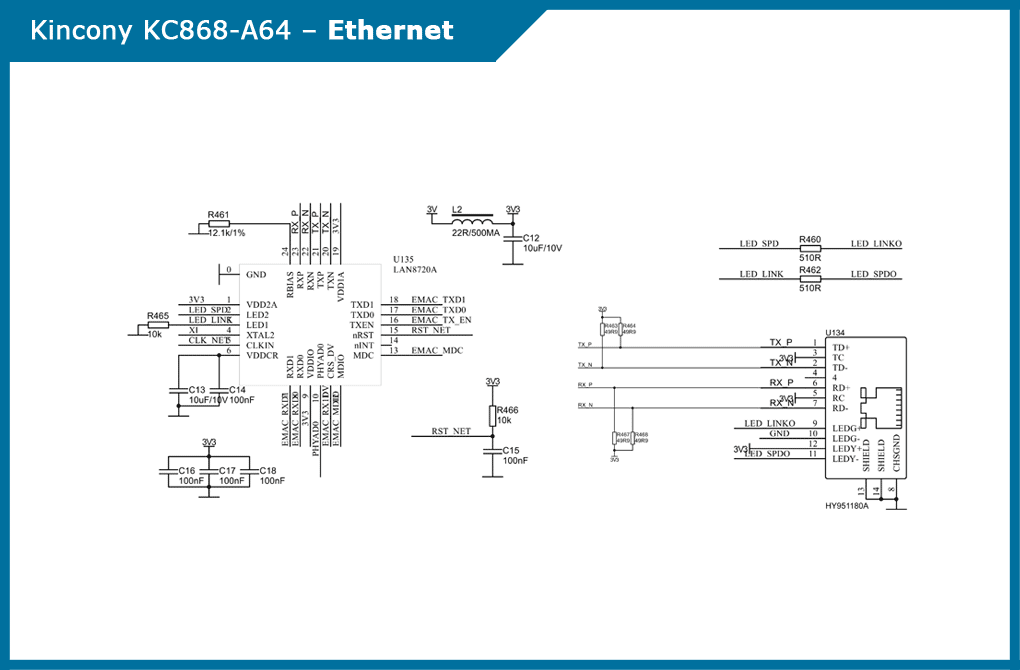
The Ethernet interface plays a very important role. Made on the standard ESP32 chip LAN8270A and according to the standard scheme. Apparently, in order to track the USB connector and here is used a vertical Ethernet connector.
RS485
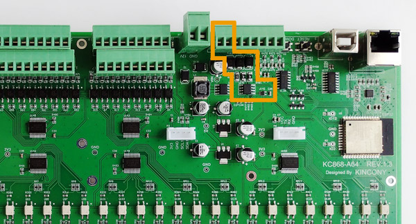
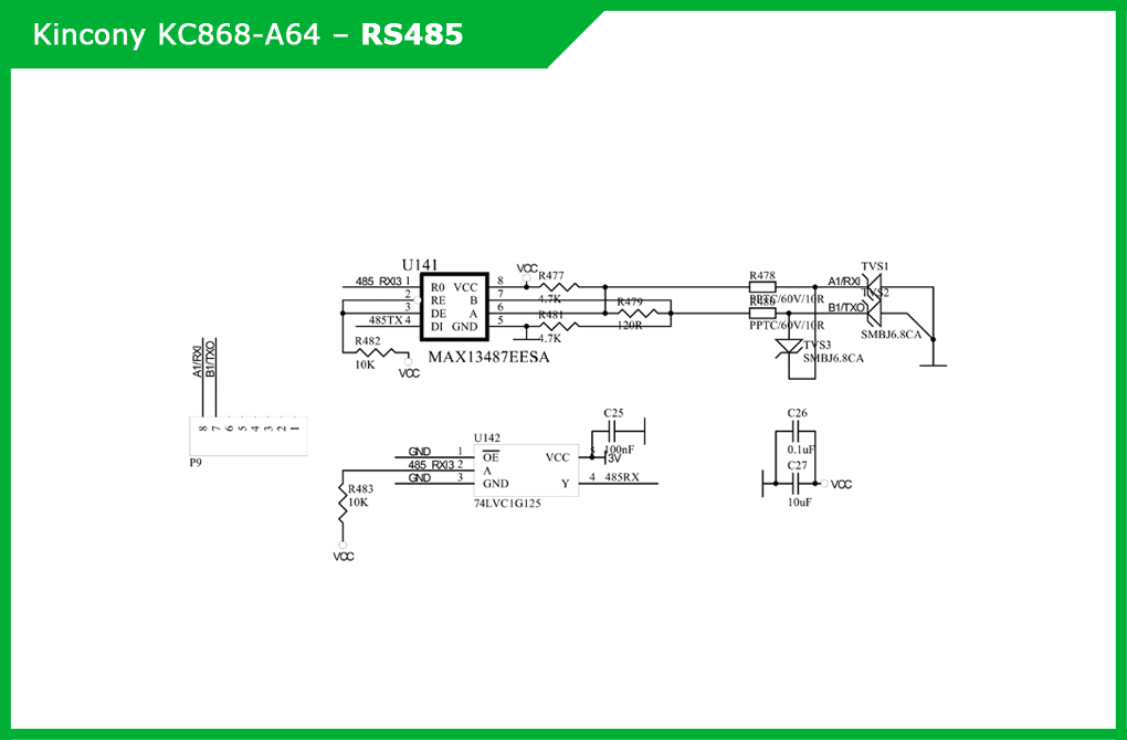
The operation of the RS485 subsystem provides the MAX13487EESA driver, the 74LVC1G125 buffer and the corresponding binding elements.
Schematic diagram of subsystem RS485:
I2C
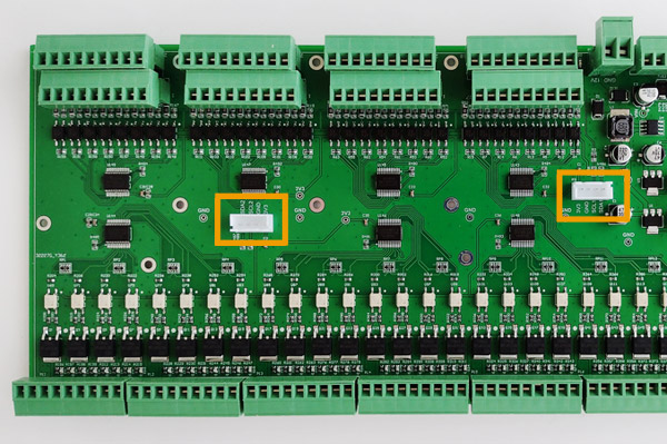
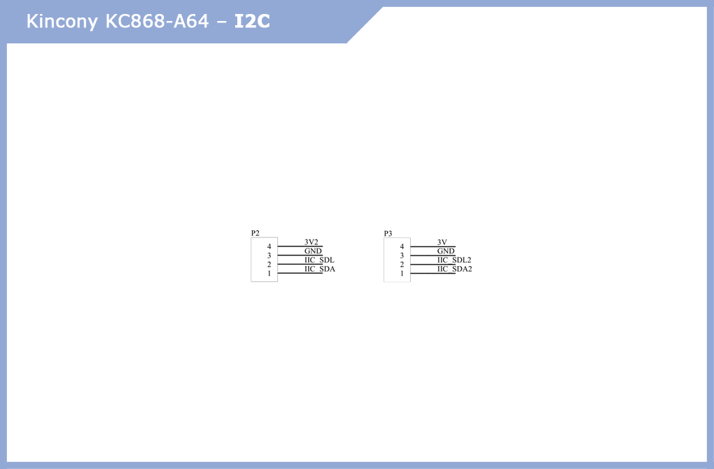
Two very useful subsystems for connecting various additional components of the I2C connector. For example, a display, additional sensors and other elements can be added.
Schematic diagram of the subsystem (connector) I2C:
Serial Port
Also a useful addition – you can connect a lot of interesting equipment’s to this connector that uses a serial interface to transmit and receive data.
Schematic diagram of the subsystem (connector):
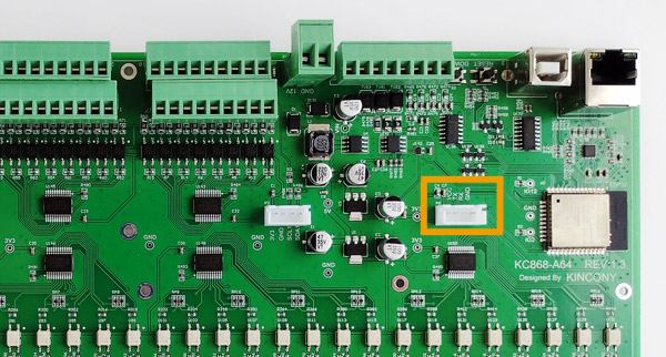
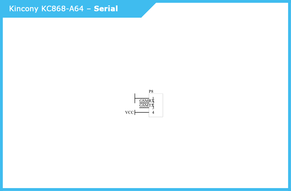
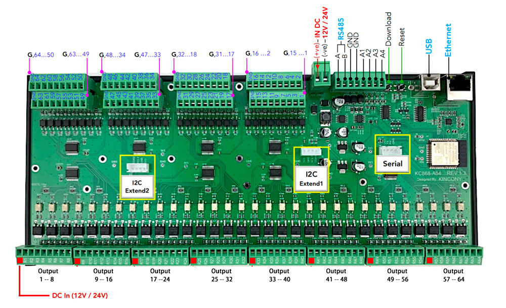
Diagram of external connector’s
Slightly modified original scheme of connectors and external connections of the KC868-A64 controller.
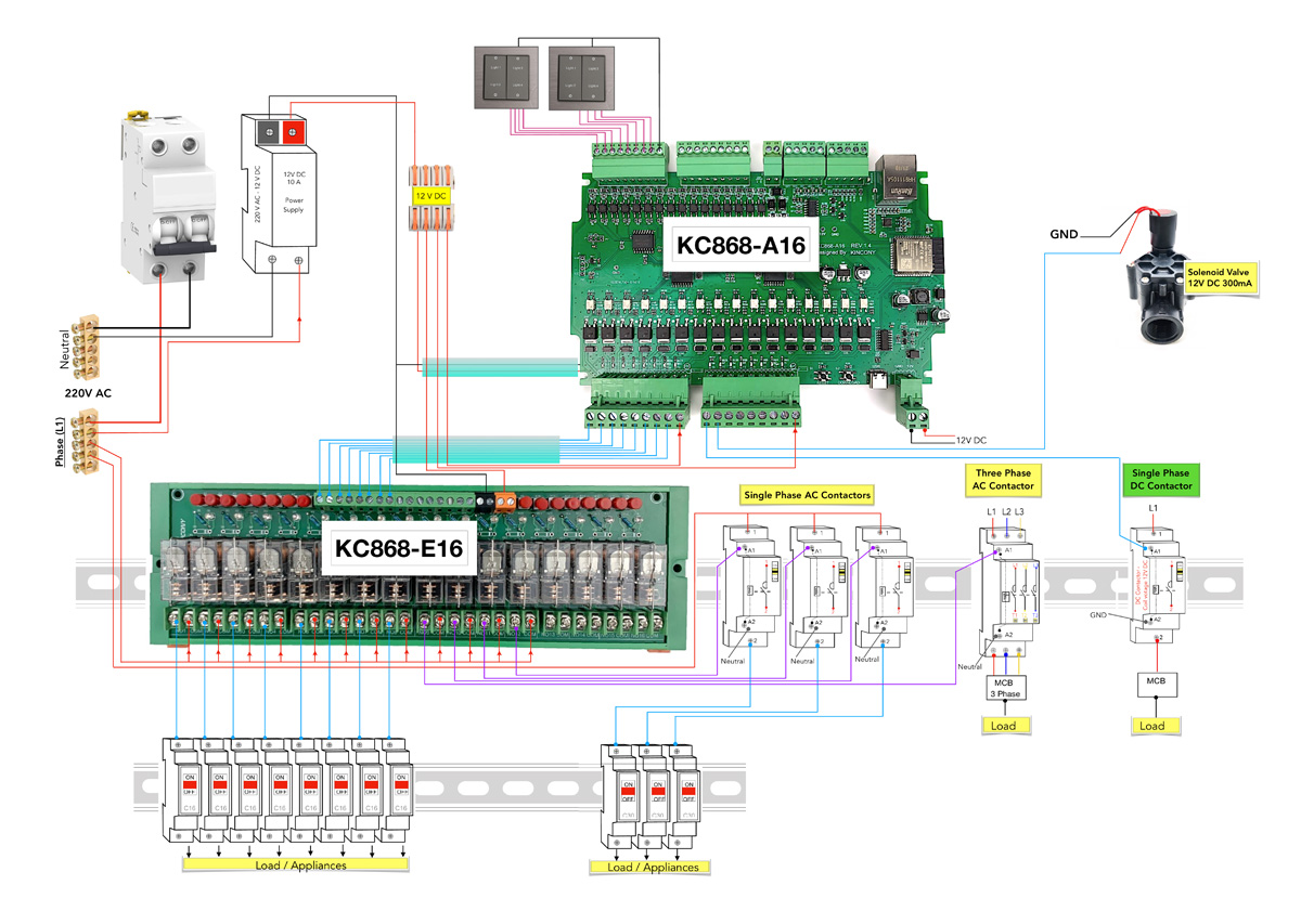
Projects with KC868-A64
I will arrange the scheme of the test project available to me for KC868-A16. Electrical connections A16 and A64 are similar and this example can be used for KC868-A64. This diagram clearly shows all the patterns of connection of different equipment – how the controller itself is powered, how the relay units are connected to it, how actuators are controlled, etc.
ESP32 pinout diagram
Pinout KC868-A64. ESP32 can provide us with GPIO’s, in my opinion, a just small number of GPIO’s is the biggest drawback of ESP32.
Conclusion
After reading this article, it will be easier for you to make the solution of problems of this type, manage information from 64 digital inputs and at the same time control 64 outputs (actuators, electric valves, …).
KC868-A64 is ready to program it through Arduino IDE or Visual studio/Platformio and upload your software into it.
