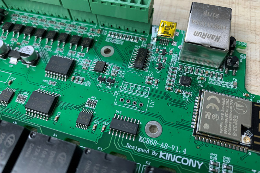
While we dealt with the universal entry-level controller on ESP32 for DIY automation Kincony KC868-A4 his older brother Kincony KC868-A8 “came up” – a much more serious device with 8 optoisolated digital inputs, 8 relays on board for controlling various equipment, an I2C connector on the board, a built-in Ethernet interface on the LAN8270A and other interesting features.
In this article, we will analyze the device of this controller in detail, but I would like to immediately note that the simultaneous presence and combination of two interfaces – wireless Wi-Fi and wired Ethernet makes the KC868-A8 a very interesting solution – the controller can work via Wi-Fi or Ethernet and use an alternative interface as a backup or work simultaneously on two interfaces (wired and wireless) and interact with different networks, etc.
In general, make yourself comfortable – another exciting journey into the wonderful world of microcontrollers and DIY automation awaits you…
Summary (previous episodes)
This article deals with one of the controllers of the Kincony ESP32 family, so before reading this article, it is recommended that you familiarize yourself with the KC868-A4 “little brother” cycle. This review of the KC868-A8 controller is in many ways a continuation of the previous series, and we will not dwell on many aspects already considered in it. It is assumed that you are already familiar with the KC868-A4 cycle.
Also, before reading this material, it is recommended that you familiarize yourself with my fundamental work “Through hardships to the stars or LILYGO TTGO T-Internet-POE ESP32 LAN8270A” (https://habr.com/en/post/547044/) in which I analyzed in detail the problems of work ESP32 with LAN8270A Ethernet interface chip. A lot of things from that article apply to the KC868-A8 as well.
In this article I will give a general overview of the KC868-A8 controller and analyze its circuitry in detail, in subsequent articles of the KC868-A8 cycle we will talk about its programming and use in real projects.
Kincony KC868-A8
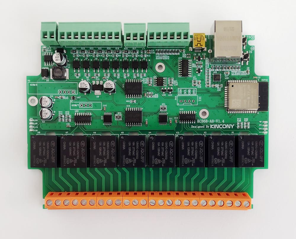
First of all, let’s get acquainted with the list of components installed on the board and the set of functional blocks that Kincony KC868-A8 provides at our disposal. First of all, this is the ESP32 module in the ESP-WROOM-32 modification with all its inherent features (Wi-Fi, Bluetooth, two MCU cores, 4 MB EEPROM memory, etc.).
In addition to the ESP32 module, the Kincony KC868-A8 board contains:
– 8 digital optoisolated inputs (“dry contact”)
– 2 analog inputs 0-5V
– 8 relays 10A 220V
– 4 contacts for connecting temperature and other sensors
– 433 MHz receiver/transmitter modules
– I2C connector
– Ethernet LAN8270A
What we lost compared to KC868-A4:
– 2 analog inputs 4-20 mA
– 2 analog outputs (DAC) 0-10V
– DB9 RS232 connector
– Infrared (IR) receiver and transmitter
– Piezoceramic buzzer (Buzzer)
At first glance, the list of losses looks impressive, but in fact, everything is not so scary. Personally, I feel sorry for only Buzzer from this list, although, of course, controllers do not have extra features and it would be better not to lose anything.
What we got (compared to Kincony KC868-A4):
+ 4 digital optoisolated inputs (“dry contact”)
+ 4 relays 10A 220V
+ 2 contacts for connecting sensors
+ I2C connector
+ Ethernet LAN8270A
Here the situation is just the opposite: it would seem that there are not so many acquisitions, but in fact they add “power” to the controller and take it to a higher level and significantly expand the range of its capabilities. Although everything, of course, depends on the needs of a particular project – in some projects, A4 will be even more preferable than A8.
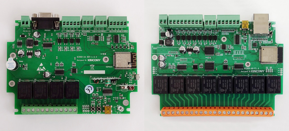
A4 and A8: two members of Kincony’s glorious family of ESP32 controllers
By the way, A8 is not yet the crowning achievement of Kincony’s creative engineering, it has a pair
“cousins from Hangzhou” – A16 and A32. So you and I will have something to do on long winter (and also spring, summer and autumn) evenings, first studying the specifications of the KC868-A series, and then programming and installing projects on these controllers.
A look inside
Kincony KC868-A8 comes with the same housing as the KC868-A4 controller (see detailed description of the housing in previous articles). Here are some photos “in the interior” so that you can imagine how the controller will look like “assembly”. View of the relay connectors:
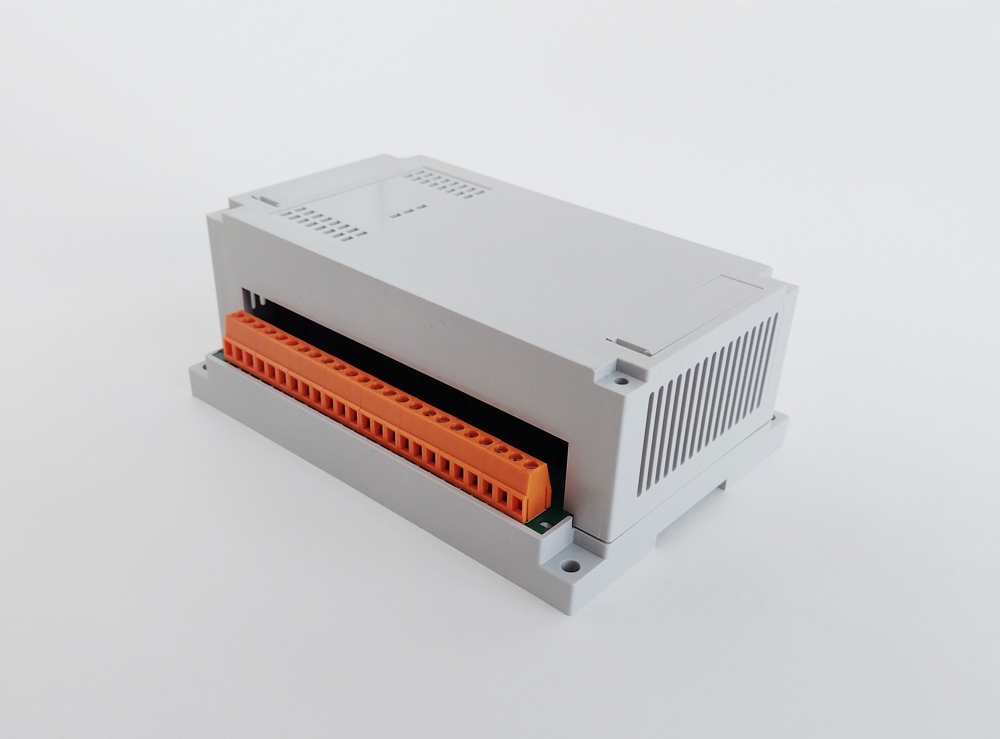
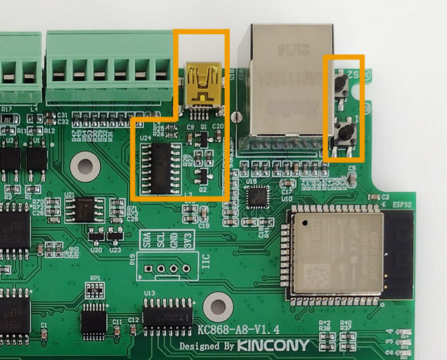
View of the input connectors, controller power supply and connection to the Ethernet network. Buttons are also visible.
“Reset” and “User” and Mini-USB connector for connecting to a computer and programming. Given the presence of an I2C interface connector on the Kincony KC868-A8 board, this case has a real chance to get some kind of display. Agree that a controller with a display is much more interesting than the same controller, but without a display.
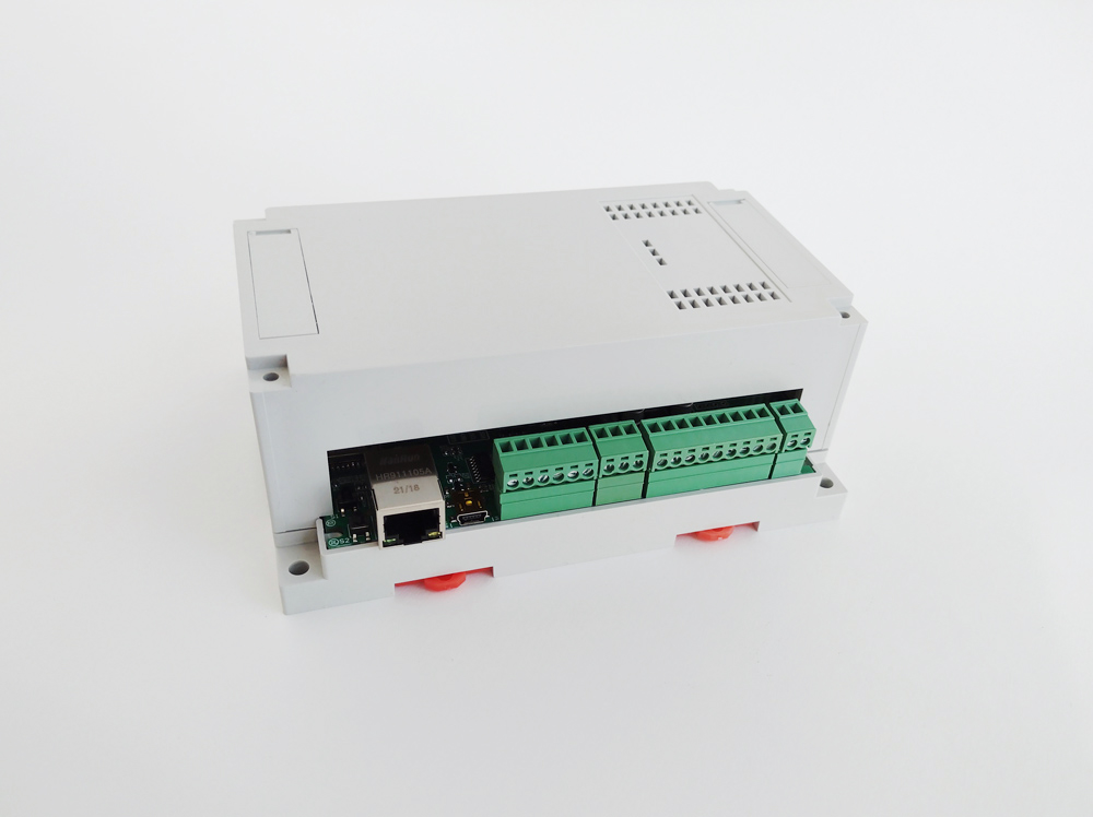
And a few more photos of the controller. With top cover remove
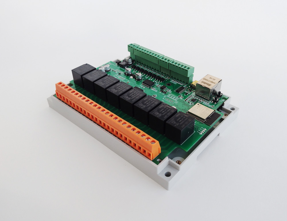
The board itself without a case. By the way, no one forces you to use a complete case and a DIN rail, you can fix the board the way you like and in accordance with the requirements of your project.
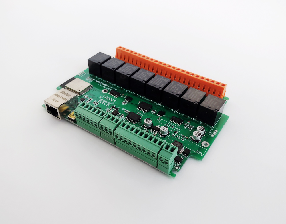
Pay KC868-A8
This concludes the general overview of the controller and proceed to the anatomy of the Kincony KC868-A8 board (please leave the children and the faint of heart). Top view of installed components. As an aesthete, I can say that Kincony’s engineers are not devoid of a sense of beauty and the design of the board (at least outwardly) looks quite harmonious.
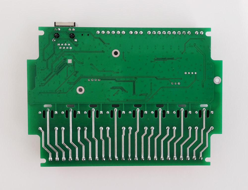
Bottom view. There is nothing special to comment on here, as we always expect the opinions of professional iron workers (as practice shows, they always have something to say).
Circuitry
We will consider the circuitry of the KC868-A8 according to the same principle that we used to describe the KC868-A4: a photo of the components on the controller board, a schematic diagram of the subsystem and my freestyle comments about this subsystem.
Since the KC868-A8 and KC868-A4 controllers are representatives of the same family, then, naturally, their circuitry is very similar, and in the process of disassembling the KC868-A8 device, I will compare it with its “younger brother” KC868-A4.
Power supply
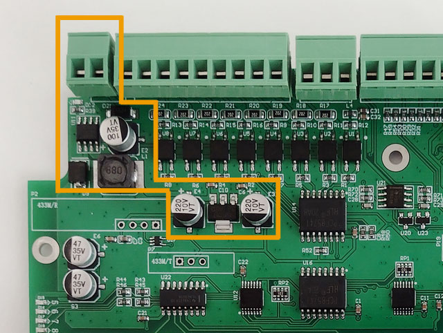
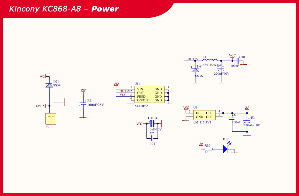
The core of the subsystem of the power supply system of the KC868-A8 controller has not undergone any major changes compared to the power subsystem of the KC868-A4 – this is still the same XL1509-5 step-down DC-DC converter chip for generating voltages of 12 V and 5 V and a linear regulator LM117- 3V3 to generate a voltage of 3.3 V (with appropriate piping).
Schematic diagram of the power subsystem KC868-A8:
Core ESP32
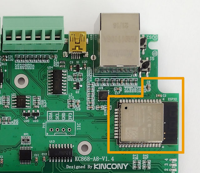
The Kincony KC868-A8 has an ESP32 module in the ESP-WROOM-32 modification, but the circuit diagram documentation indicates the ESP32-S modification. Since these are practically the same thing, then, apparently, the manufacturer soldered into the boards those ESP32 modules that are currently in its warehouse. This is just my guess, but it’s most likely true. This is indirectly confirmed by the fact that ESP32-S is installed in the A4.
Schematic diagram and pinout of the core (ESP32) of the controller:
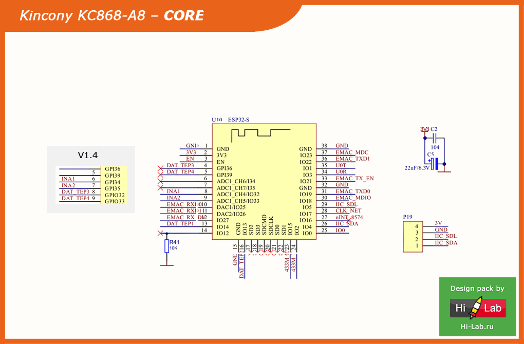
We will talk about pinout, GPIO distribution and programming in the next article of this series.
USB/CH340
The design of the subsystem for connecting to a computer and programming KC868-A8 almost completely repeats the corresponding subsystem KC868-A4 (with minor exceptions). Here is the same Mini-USB connector, CH340C chip and two buttons – “RESET” and “USER”.
Schematic diagram of the subsystem USB / CH340 controller

Digital inputs
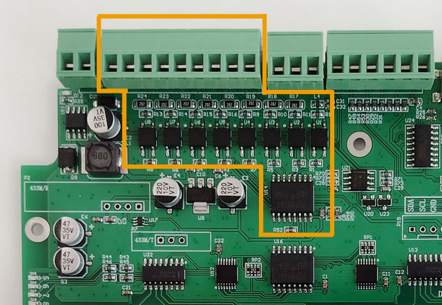
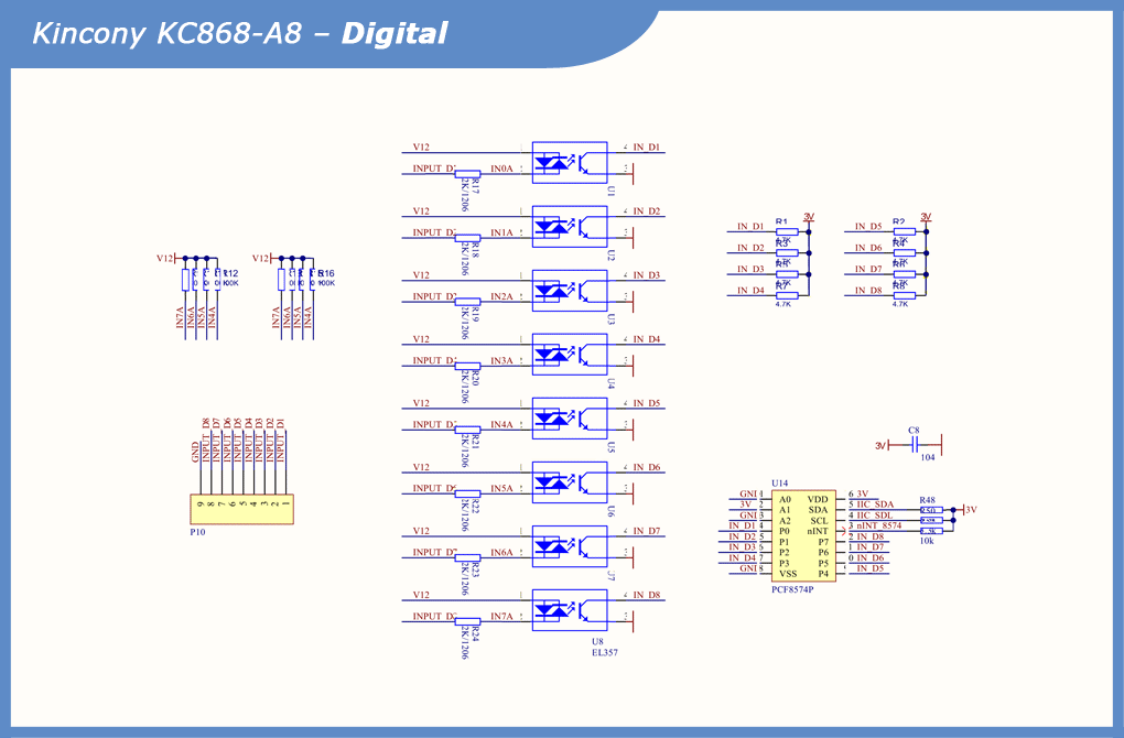
The Kincony KC868-A8 board has 8 optoisolated digital inputs on EL357 optocouplers. The LEDs that were on the KC868-A4 disappeared, apparently due to the lack of free space on the board. This is a pity because it was very convenient to visually control the state of the inputs.
The KC868-A8 also uses a digital I/O expander with an I2C interface PCF8574P, which can only be welcomed on a board with ESP32 with its (dramatically) limited number of GPIOs.
Schematic diagram of the digital input subsystem:
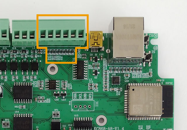
Analog inputs
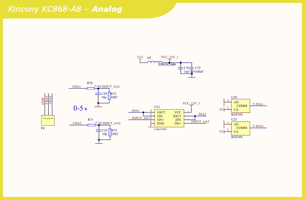
On the analog side, the KC868-A8 board suffered significant losses and lost two of the four analog inputs, leaving only 2 inputs for 0-5 V signals. This is certainly sad, but in most cases it is not fatal. Signal shaping is entrusted to the input stages, the LM258D dual op amp and the BAT54S Schottky diodes.
The voltage VCC_12V_1 is immediately formed.
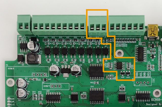
Schematic diagram of the analog input subsystem:
Relays
The photo clearly shows that the relay subsystem occupies more than half of the Kincony KC868-A8 controller. 8 relays are serviced by 74HCT14 microcircuits with inverting Schmitt triggers and ULN2003A with Darlington transistor matrices. On both edges of the board there are groups of indicator LEDs.
The very interaction with the ESP32 microcontroller is carried out using the expander
digital inputs/outputs with I2C interface PCF8574P (same as in the case of digital inputs).
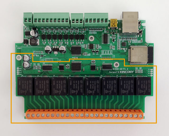
Schematic diagram of the relay subsystem:

Temperature/humidity sensors
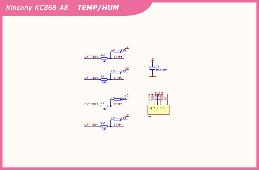
Here we have a 6-pin block with 4 connectors for connecting temperature and other sensors. This is a big step up from the similar single contact of the KC868-A4 controller. Here we have complete freedom of action – you can connect any suitable sensors or networks of several sensors.
You just need to remember that all the contacts on the board are pulled up to a voltage of 3 V. In extreme cases, you can remove the pull-up resistors from the board and get “clean” GPIOs, to which you can connect the equipment you need.
Schematic diagram of the sensor connection subsystem:
RF module 433 MHz
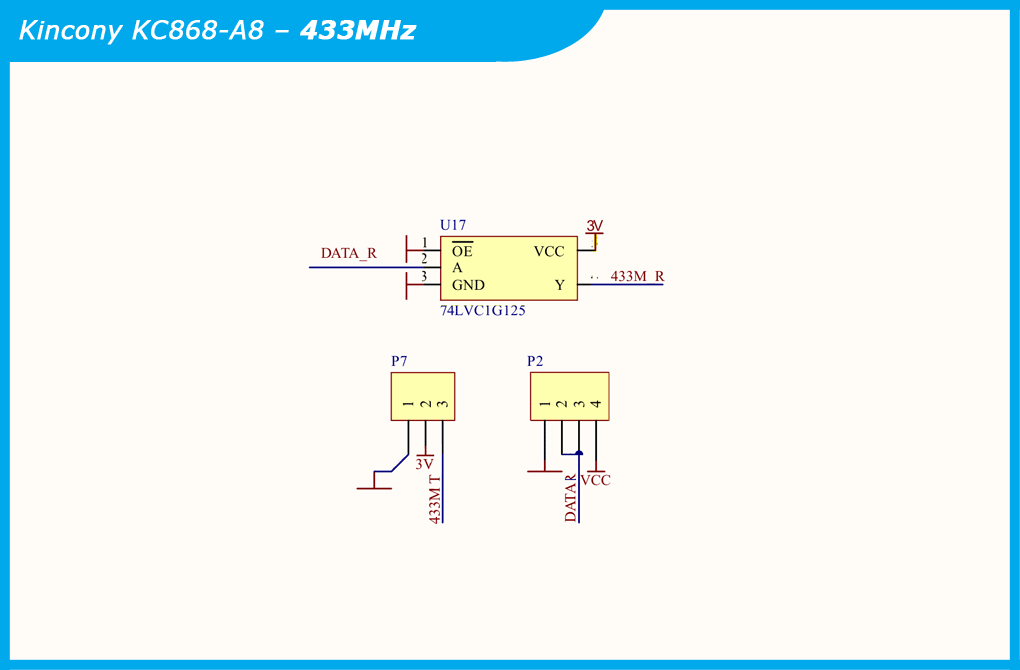
Here we see unsoldered connectors for connecting modules at 433 MHz (see details in the series about KC868-A4). You can connect modules and get a connection at 433 MHz, but not everyone needs such wireless connections – you can connect something else to these contacts instead of 433 MHz modules that you need in a particular project.

Schematic diagram of the subsystem for connecting wireless modules at 433 MHz:
Ethernet
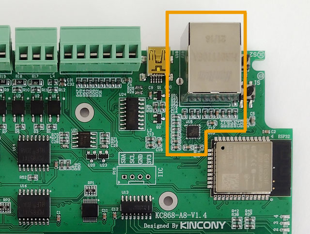
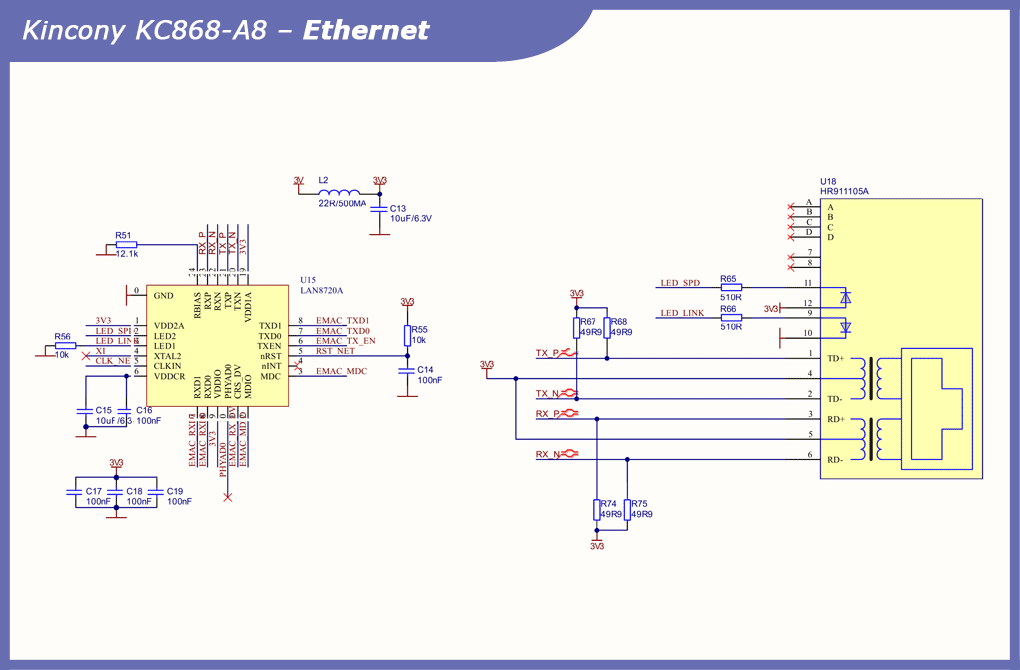
And finally, the main “feature” of the Kincony KC868-A8 controller is Ethernet on the LAN8270A chip. This is a technology that works great on the ESP32, and in this case we get the opportunity to connect the controller via Wi-Fi, or Ethernet, or simultaneously via two interfaces, or use the second interface as a backup, etc. Here, the possibilities are limited only by your imagination (the imagination of the firmware programmer for KC868-A8).
Among the disadvantages of using the LAN8270A as part of an ESP32 controller is that the Ethernet chip occupies as many as 9 GPIOs from the already extremely meager number of free pins of this microcontroller. In this case, port expanders for inputs and relays save the situation.
Schematic diagram of the Ethernet subsystem:
I2C
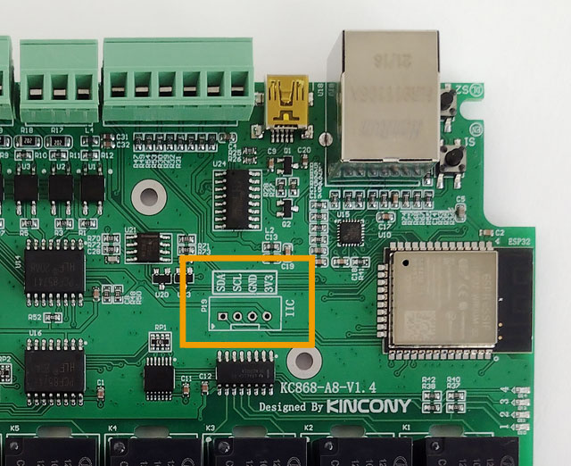
A big gift from the developers of the Kincony KC868-A8 controller was a connector for connecting
I2C hardware. Thanks to this, you can connect some of your I2C-compatible components to the controller, at least a display, which will positively affect both the appearance and usability of your controller.
Conclusion
The more I work with Kincony’s KC868 series controllers, the more I like them. Of course, a lot of things could be fixed in them, but even in the form in which they are, they are already excellent solutions for small automation and DIY projects.
And in the next article, we will analyze the pinout of the KC868-A8 bit by bit and learn how to program its components (functional blocks).
