I don’t know about you, but my first association when looking at the Kincony KC868-AG is a hockey puck. In fact, this is another IoT controller from Kincony based on the popular ESP32 microcontroller, designed for IR control of home equipment and additionally equipped with a 433 MHz wireless receiver and transmitter for interacting with devices like weather sensors, smart sockets and the like.
In many ways, the KC868-AG resembles the KC868-Uair controller we have already reviewed, but there are some differences. We will talk about these differences and how you can use the KC868-AG further.
KinCony KC868-AG
KC868-AG has on board ESP32 in ESP-WROOM-32 modification (4 MB built-in EEPROM memory) and can work with Wi-Fi and Bluetooth. In addition, KC868-AG contains:
- Piezoceramic buzzer (Buzzer);
- Infrared (IR) receiver;
- Infrared (IR) transmitter;
- Receiver module 433 MHz;
- Transmitter module 433 MHz;
- Internal connector with 12 free GPIOs;
- Mini-USB connector for power/communication with a computer;
- Reset button RESET;
- 3 indicator LEDs (not soldered in my copy of KC868-AG).
Compared to KC868-Uair, KC868-AG lost:
- Built-in temperature sensor DS18B20;
- Indicator LEDs WS2812;
- Connector for connecting external I2C sensors.
In fact, all these losses are insignificant – thanks to free GPIOs, adding a temperature sensor or WS2812 LEDs will not be difficult. The situation is somewhat worse with free space in the case – the KC868-AG has much less space and not every sensor or other component will fit inside.
Purpose KC868-AG
Of all the above equipment installed in the KC868-AG, the main and “backbone” are the IR receiver and transmitter. Compared to the KC868-Uair, the number of infrared emitting LEDs has been increased and their location has been improved, and the case itself is “sharpened” for working with IR equipment – the cover is not actually black, but is made of IR transparent (red) plastic, through which it passes emission of control IR LEDs.
All other components installed in the KC868-AG are optional and only expand the basic functionality for IR control of home devices. In general, we fill in the required firmware and we get the opportunity to both receive and decrypt commands from IR control panels, and issue IR commands to control surrounding devices.
The firmware, respectively, can be any, and you can organize any logic of work both for decoding and storing IR commands, and for managing your devices – by events, by schedule, by sensor readings, etc.
Well, the receiver and transmitter at 433 MHz can expand the capabilities of our “washer”. In addition, thanks to the free GPIOs, you can further increase the capabilities of the KC868-AG and add the equipment you need, for example, nRF24 or LoRa wireless modules (we will talk about this in more detail later).
Appearance and cover
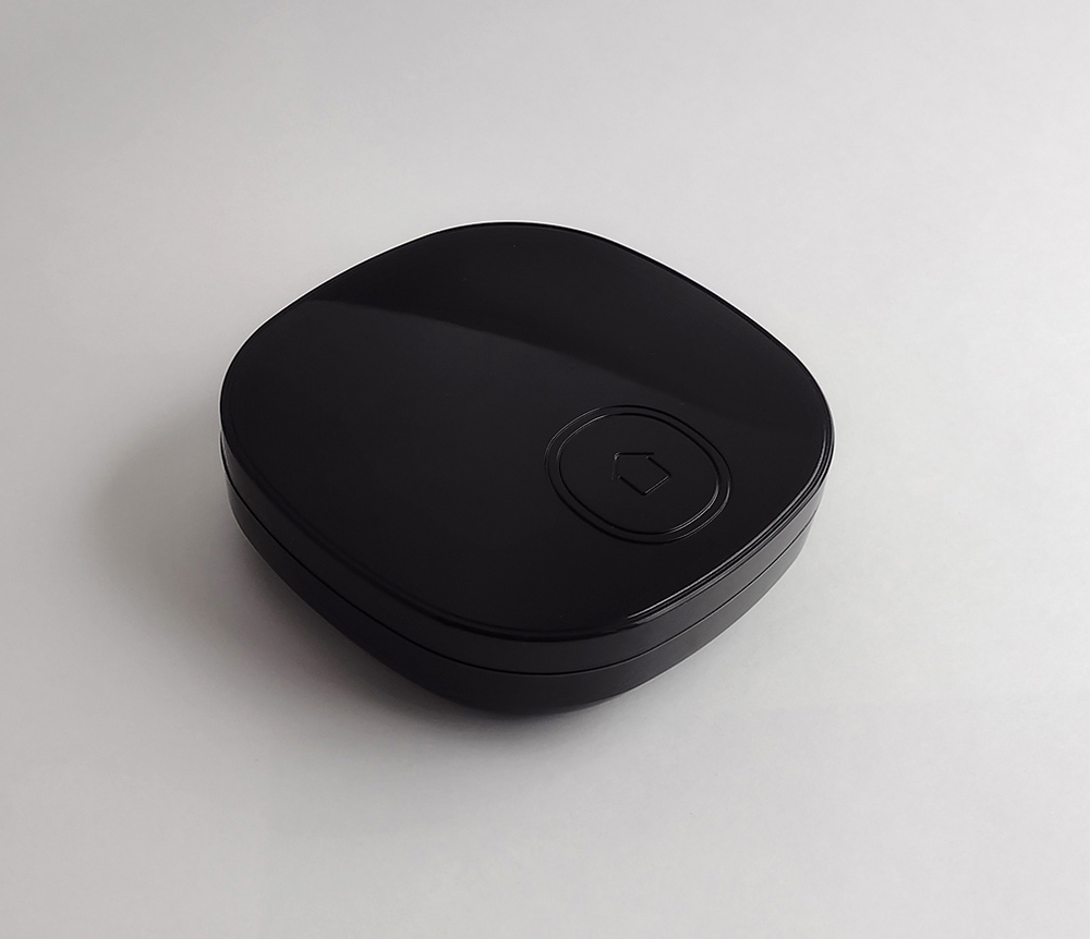
In general, I have no complaints about the design of the KC868-AG – the controller has a characteristic look, characteristic of such devices. I can imagine such a device in almost any interior. Although, of course, the design could be better.
The “button” with an arrow (or is it a stylized house?) is an imitation and is not pressed, it is just a decorative design element. Although, it is possible that in some versions of the case there is a real button in this place (but not in our case).
Of the jambs, it can be noted that, despite the presence of a protective film, when it was removed, the upper polished surface of the case turned out to be somewhat worn. How it was possible to spoil the presentation of the product under the protective film remained a mystery to me.
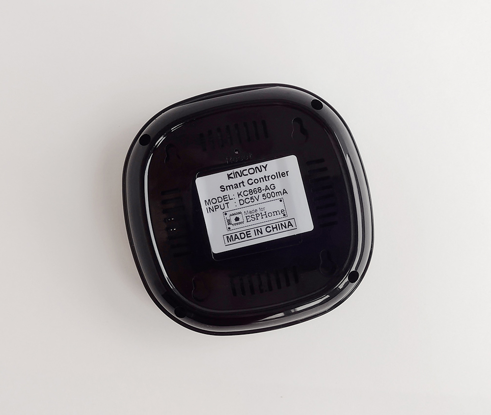
Case view from below. You can see 4 mounting holes for screws, ventilation holes, a manufacturer’s sticker and a RESET button (right above the KINCONY inscription).
It is worth noting here that the KC868-AG is that rare case when you do not need to have the skills of a level 80 repairman to disassemble the case and the device itself – everything is disassembled by simply unscrewing a few screws, which is very nice after the torment with disassembling the KC868-Uair.
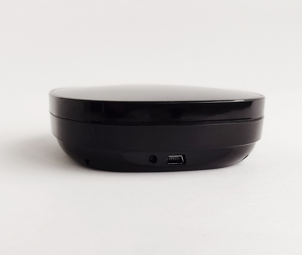
On the side you can see the Mini-USB connector and the power indicator. Through this Mini-USB connector, power is supplied to the KC868-AG and the device is programmed.
Let’s see what’s inside
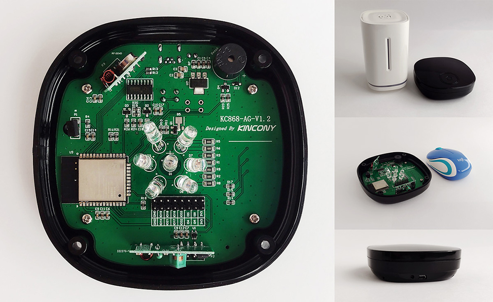
Unscrew 4 screws and remove the top cover. We see the board inscribed in the geometry of the case and some free space that can be used to add the components you need. With free space, you can’t really clear up, but to add radio modules, smart LEDs and similar devices, there should be enough space.
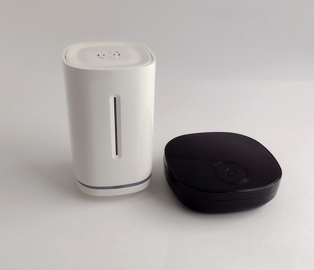
For size comparison: KC868-AG and M187.
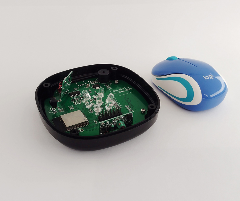
Top view of the board installed in the KC868-AG case. 4 screws are visible, on which the board is attached. We unscrew the screws and remove the board from the case. Everything is simple, no tricky latches and problems with disassembly.
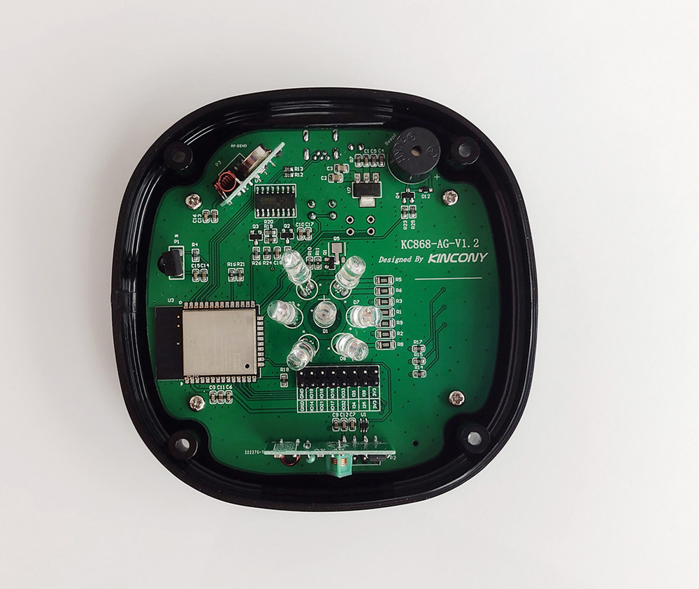
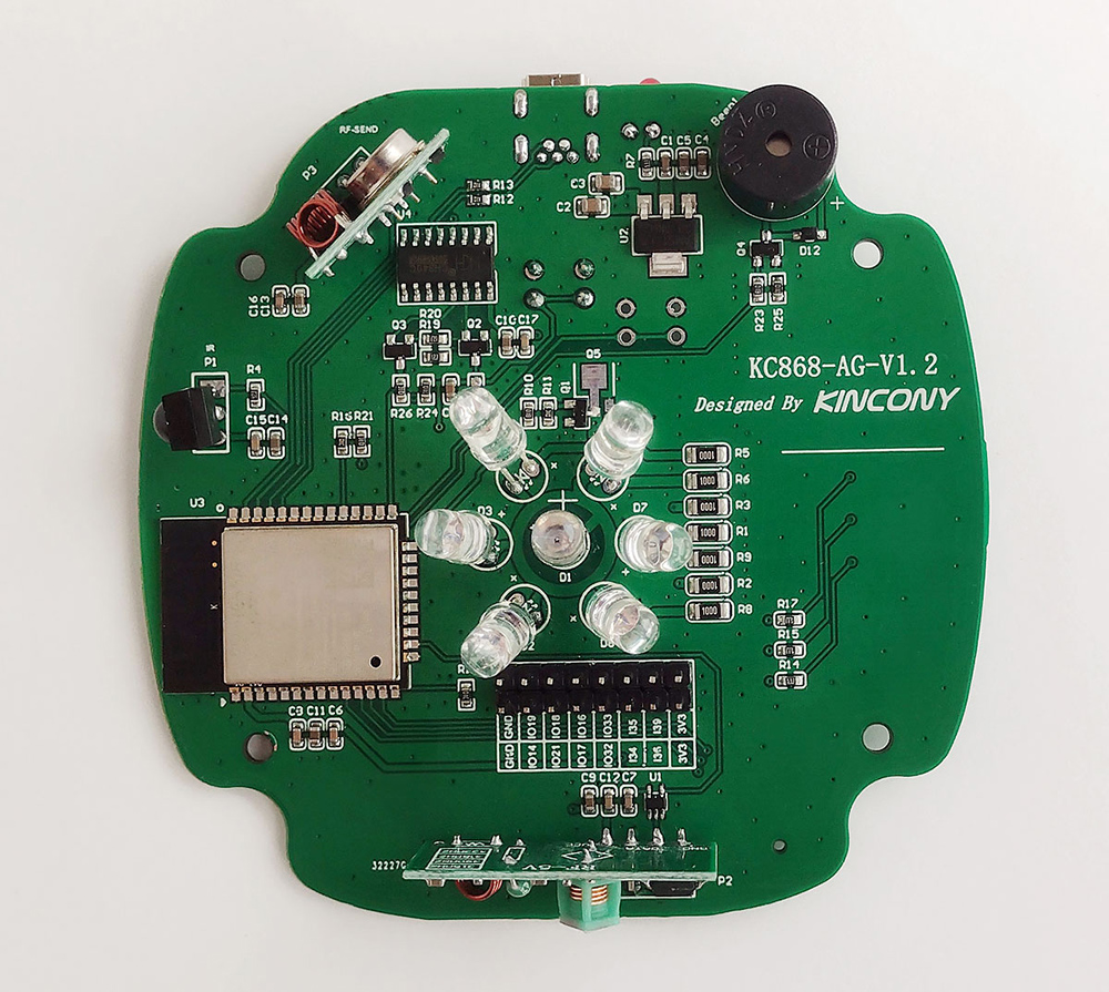
View of the board removed from the case. A group of 7 infrared LEDs stands out in the center. The number and location of the diodes suggests that there will be no problems with IR control.
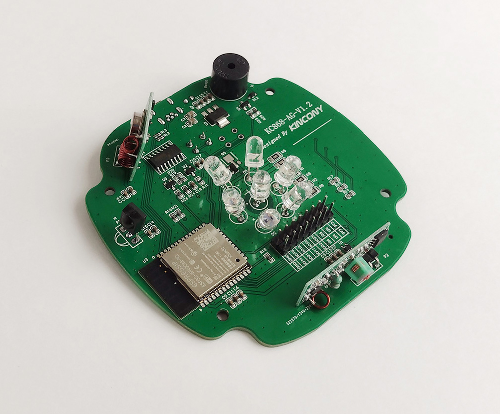
There is also a connector with free GPIOs for connecting. The connector itself was soldered by me, in the initial state from the factory the connector was not soldered.
Circuitry KC868-AG
Now let’s move on to the analysis of the Kincony KC868-AG circuitry. Top view and close-up of installed components. A little free space (under the inscription with the name of the controller) pleases – here you can place additional components.
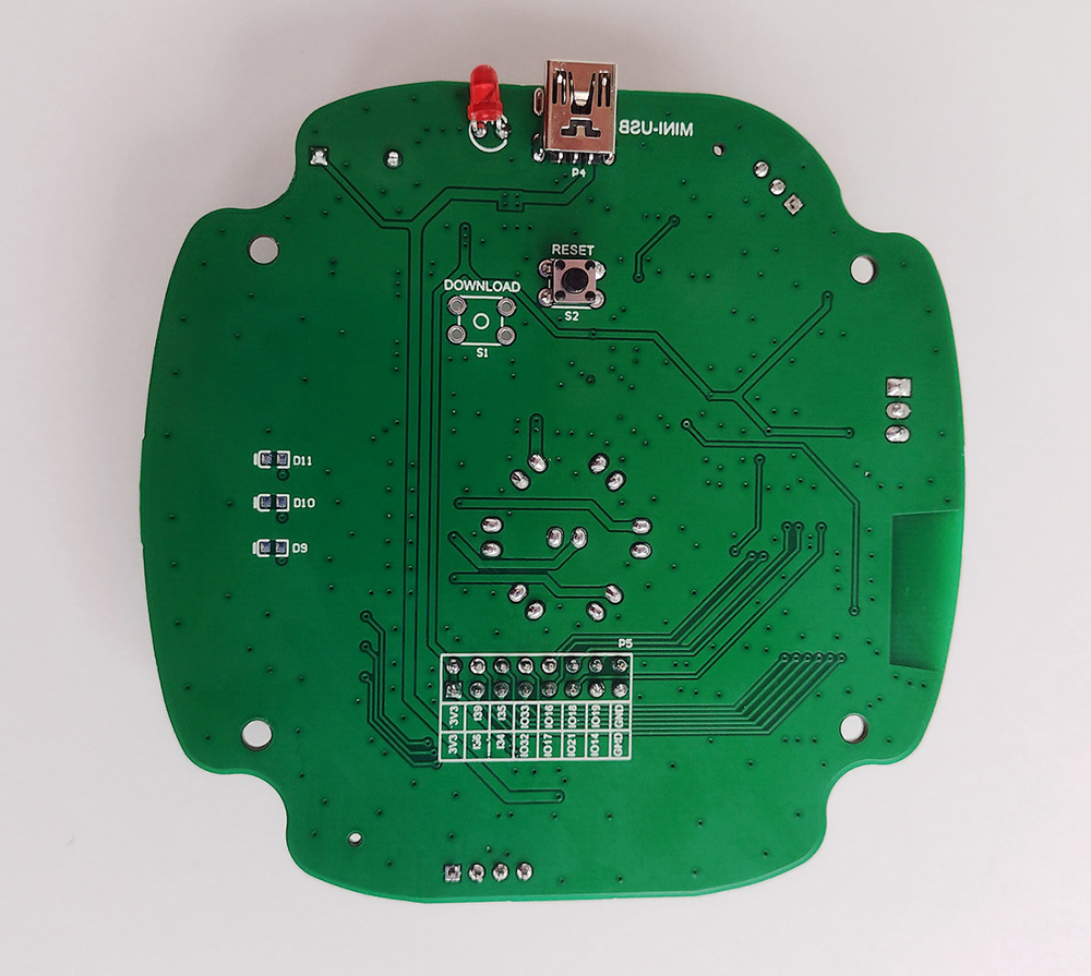
Bottom view. The DOWNLOAD button and D9-D11 LEDs are missing, as well as the MINI-USB inscription is upside down. The foil window on the PCB for the ESP32 antenna could have been a little bigger.
▍ Power supply
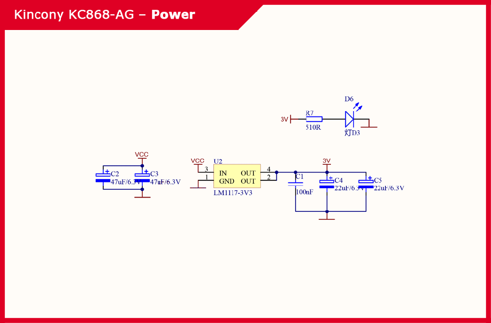
The Kincony KC868-AG power subsystem is extremely simple, it uses only the LM117-3V3 linear regulator with the appropriate piping to generate a voltage of 3.3 V. Plus, an LED indicating the presence of supply voltage has also been added.
▍ ESP32 core
The Kincony KC868-AG uses the ESP-WROOM-32 microcontroller, this functional block includes a couple more filter capacitors located in close proximity to the ESP32.

▍ USB/CH340
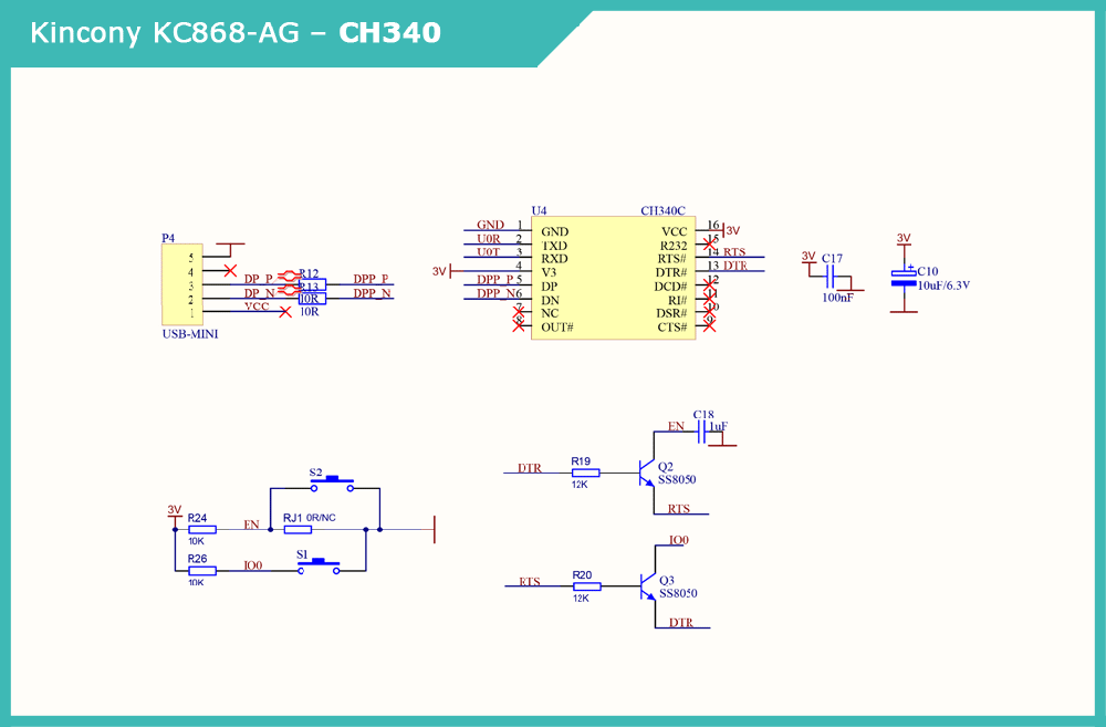
To connect to a computer and program the KC868-AG, the board has a Mini-USB connector and a CH340C USB/Serial converter chip, as well as the corresponding harness for automating sketch loading. The DOWNLOAD button is not soldered on the board, but if necessary, you can add it yourself.
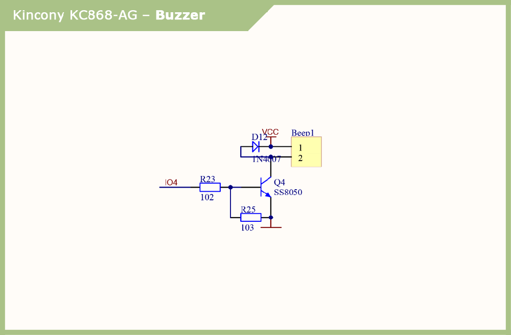
▍ Buzzer
Buzzer, just Buzzer. A simple, but very useful addition to the functionality of our controller, allows sounds (including those with tonal coloring and even simple melodies) to notify users of various events.
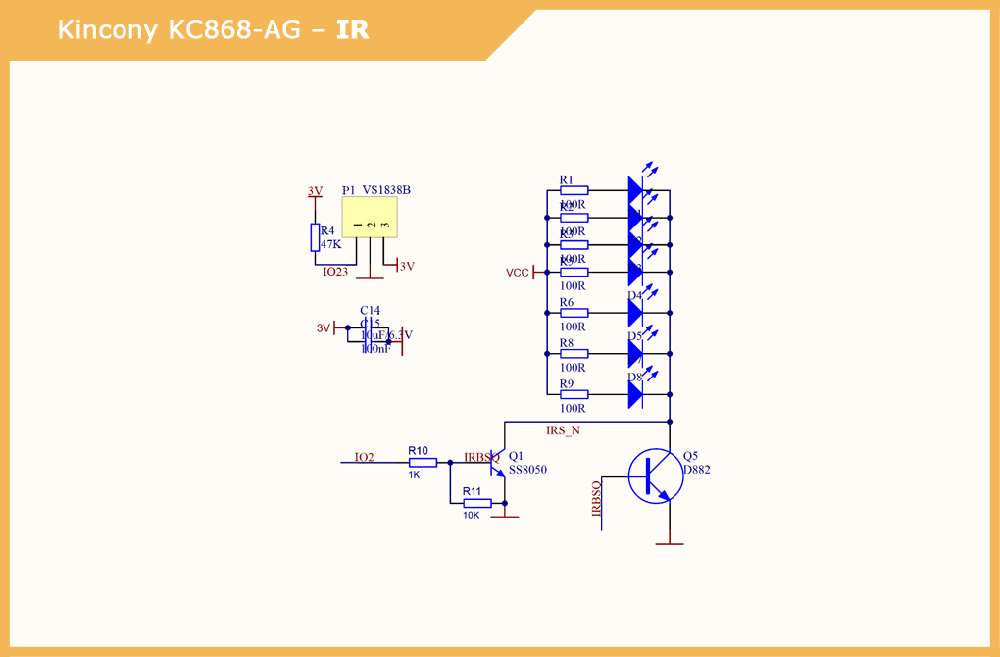
▍ Infrared receiver/transmitter
Kincony KC868-AG is equipped with an infrared receiver and emitter. The VS1838B sensor is used as an IR receiver. And as emitters, 7 emitting IR diodes controlled through transistors are used.
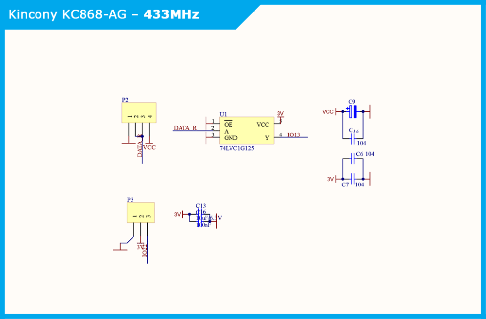
▍ 433 MHz modules
The buffer element 74LVC1G125 is used to generate and supply the controller with an input signal from a 433 MHz receiver, and the output signal to a 433 MHz transmitter is fed directly. There are also capacitors here to smooth out ripples and transients for powering radio modules.
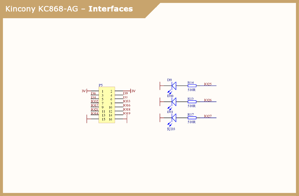
▍ Interfaces
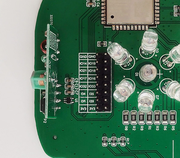
The KC868-AG board has a connector with 12 free GPIOs, ground and 3.3V voltage, to which you can connect your additional equipment and components. Here you can also see the GPIO25-27 pins, which, according to the diagram, are designed to control LEDs, but in reality, these LEDs are not soldered on the board.
Pinout
The photo shows the pinout of the P5 connector with free GPIOs for connecting.
And then the pinout of the ESP32 microcontroller from which you can get a (clear) idea of \u200b\u200bwhat and how is connected there.
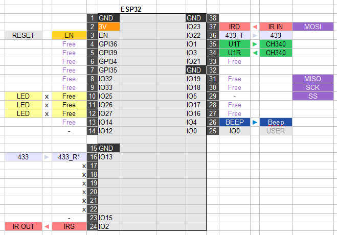
From this pinout, you can see that the KC868-AG has a huge number of free GPIOs for connecting (which is good news). On the other hand, it can be seen from the same pinout that the SPI interface pins are again incorrectly distributed by Kincony engineers – GPIO5 and GPIO23 are occupied.
Getting GPIO23
In the diagram below, I showed one of the ways to get GPIO23 on the KC868-AG board, which seemed to me the easiest to implement for an inexperienced user. We cut the track, remove the resistor R4 and solder the wire to one of the freed pads of the resistor. On the other side of the board, we solder a regular (not SMD) 47K resistor instead of the remote one.
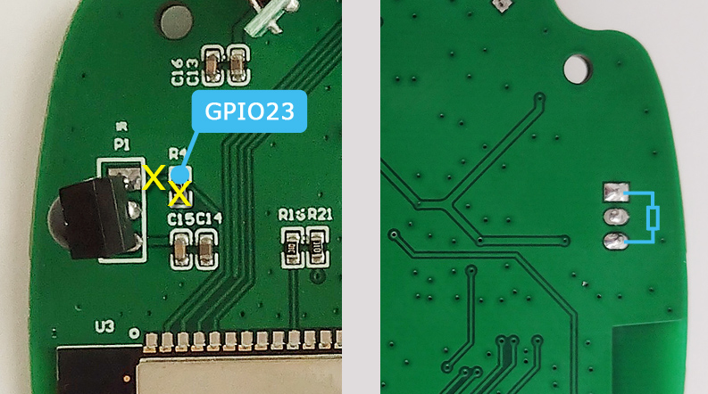
To get GPIO5, just remove the R16 resistor and solder the wire to one of the freed pads (the one that goes to the ESP32 microcontroller).
After these simple manipulations, you can connect any SPI components to the KC868-AG. Thanks to Kincony for keeping us busy and taking care of our creative thinking and soldering skills.
3 LEDs or 3 GPIOs
As I noted above, there are no D9-D11 LEDs on the board. In general, the presence of these (indicator) LEDs on the bottom side of the board raises doubts – why are they needed there at all, if their glow is almost invisible. Therefore, we will not worry about them and it is better to add 3 more free GPIO25-27 to our arsenal.
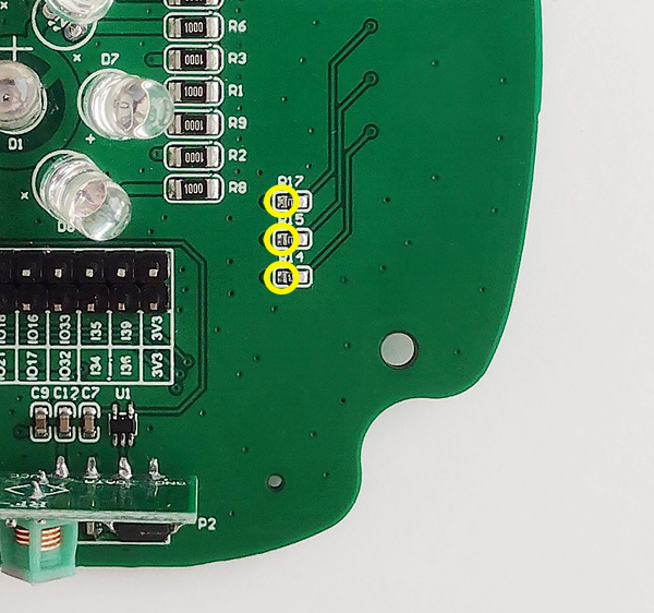
To do this, you can simply remove the SMD resistors R14, R15, R17 and solder the wires to the released pads, as shown in the photo above. As a result, we will have at our disposal 3 more free GPIOs (25-27).
Usage patterns
I see two possible use cases for KC868-AG:
- Do not touch anything, just upload some (your own or third-party) firmware and use the KC868-AG as an IR controller to control household equipment (TVs, air conditioners, etc.).
- Connect the components you need to the board (sensors, wireless modules, indication, etc.) and use the KC868-AG as the center of your “smart home”. What and how this center will do depends only on your programming skills and your imagination.
Conclusion
In general, Kincony KC868-AG as a mini smart home controller has the right to exist and may well become a useful device in your home. It is also a perfect trainer for learning microcontroller programming and DIY experiments for curious and creative people of all ages.


