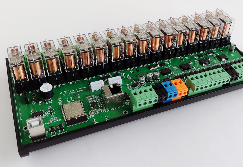
I’m looking at the KC868-E16S and I can’t understand what it reminds me of anymore – a high-class vacuum tubes amplifier, a cyberpunk space device or an artifact from the Soviet stepper PBX. Maybe I prefer the cyberpunk option, if you add a little copper and something like Stirling’s engine, it would be pretty cool. The weight of the baton 16 gives the controller a certain monumentality, it seems as if you are holding the “real thing” in your hand. Yes, and the rest of the stuffing in the style of the KC868 series is very interesting, I invite you to get acquainted with the content of KC868-E16S and see what is and how it is arranged there …
(By the way, have you noticed that the letter “A” in the controller name has been changed to “E”? This species transparently hints to us that Kincony himself calls this product a class of “smart relay blocks”, I would even say “very smart relay blocks”.)
Kincony KC868-E16S
From a functional point of view, the KC868-E16S has a standard kit for KC868 series controllers, including Ethernet and RS485 interfaces, which together with ESP32 makes it a potentially very powerful solution for your IoT projects. It is only about the firmware, which will be able to use all the features provided by the Kincony KC868-E16S. Here you can pick up some popular firmware for ESP32 or the more it impresses me, create it yourself and do everything you want.
Next, I give a list of all parts and subsystems included in KC868-E16S:
- ESP32 (ESP-WROOM-32)
- 16 digital optocoupler inputs (“dry contact”)
- 16 digital input test buttons
- 2 analog inputs 0-5 V
- 2 analog inputs 4–20 mA
- 16 relays 16A 220V (NO, COM)
- 16 RELAY status LEDs
- RS485 interface
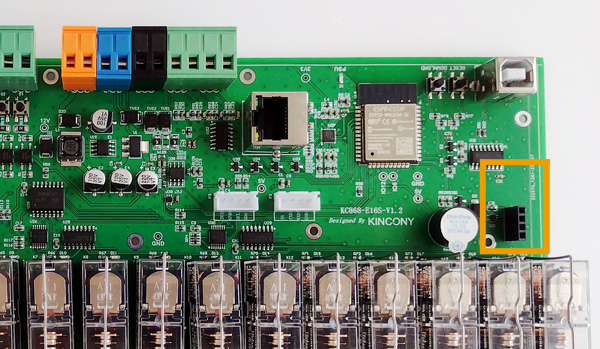
- 433 MHz receiver connector
- Ethernet LAN8270A
- Piezoceramic buzzer
- I2C connector
- Serial Port
- USB programming port
- Buttons for reset and download
- Power connector 12 V
Impressive set, with the help of which you can carry out many interesting automation projects. ESP32 (Wi-Fi and so on), configuration from 16 inputs to 16 relays, 4 analog inputs, a receiver of 433 MHz, a wired Ethernet interface, RS485, as well as various trifles such as piezo-ceramimic buzzer, buttons and separate I2C and serial connector for connecting accessories – all this is located on board KC868-E16S.
Layout and device
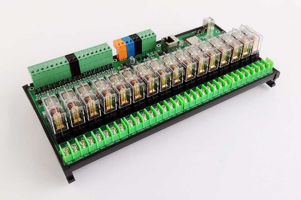
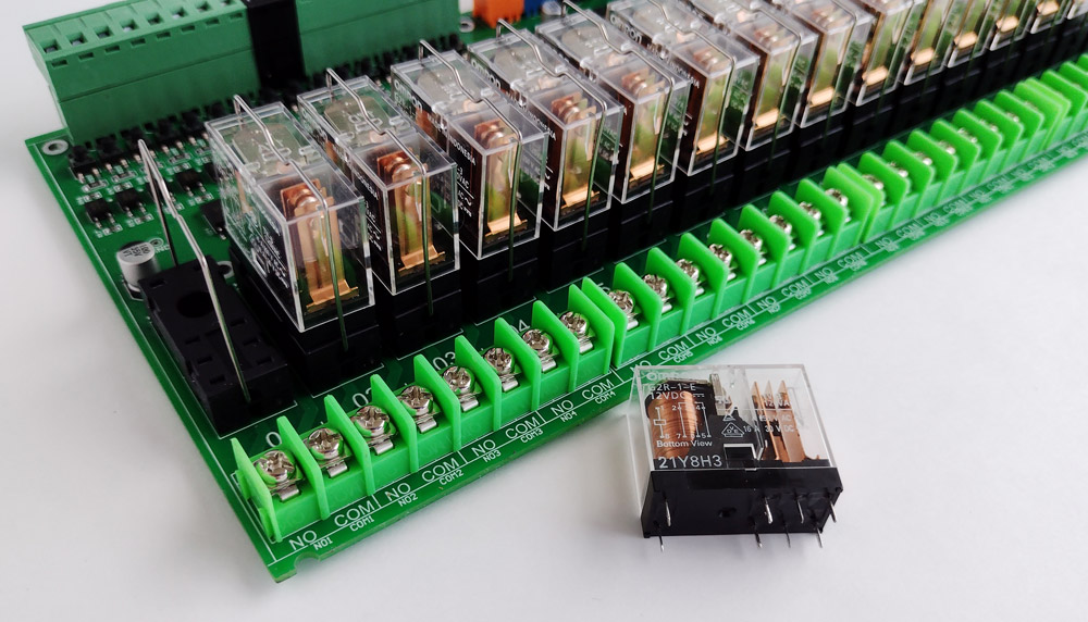
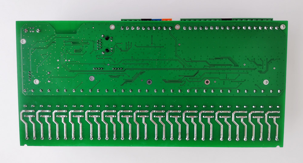
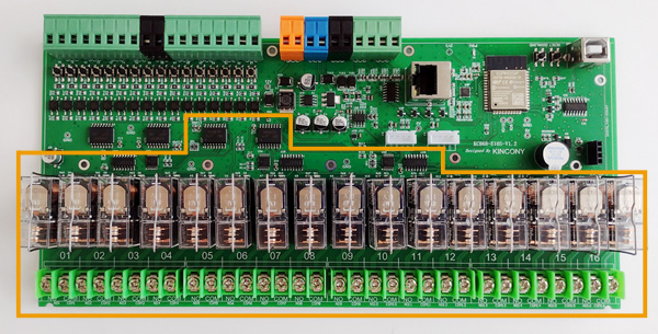
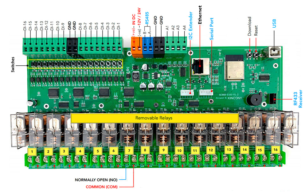
The KC868-E16S looks even more impressive. Powerful connectors for connecting loads give it a “professional” look. True, instead of 3 contacts for the relay, only 2 (NO and COM) are used, which somewhat narrows the range of application of this controller and in some cases can cause a headache for developers. But for powerful connectors and 16 relays on the board you have to pay something. The relays themselves are made as replaceable, inserted in bases. To ensure good contact in vibrational conditions, each relay is additionally fixed with a spring. Such a solution captivates with simplicity and speed of replacement. If any relay fault, the old one is simply taken out and a new one is inserted in its place. (Of course, before it is necessary to turn off the power supply of the e controller).
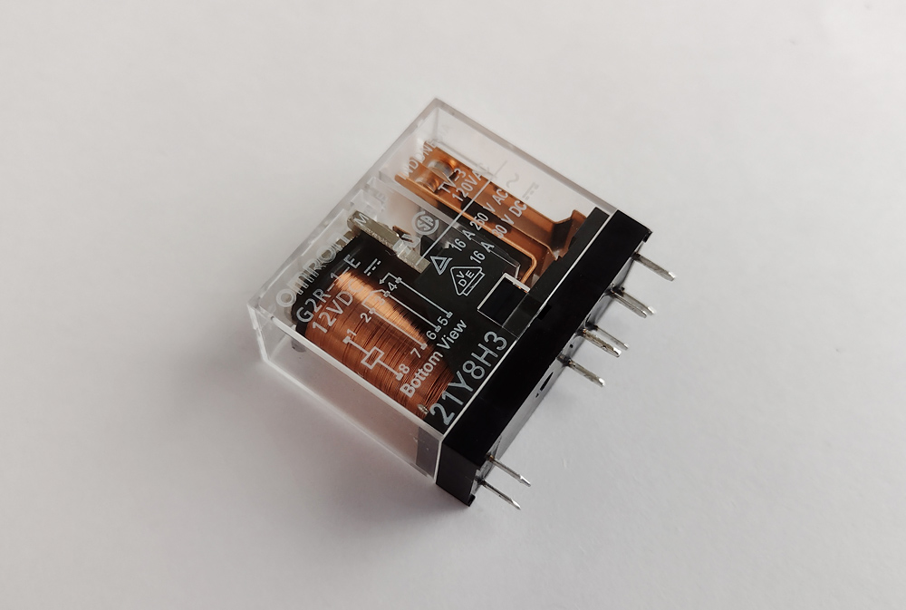
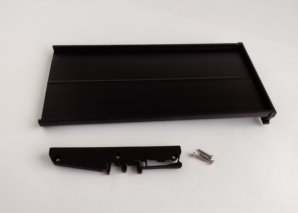
Below is a separate photo of the relay: its design, marking and technical characteristics are clearly visible. The control panel is installed in a special plastic housing with the possibility of connecting to the DIN rail. Everything is mounted and disassembly is very simple, without any effort. Of the shortcomings of this solution, it can be noted that the controller plate remains completely open and over time can be covered with dust, which can lead to various problems.
Motherboard Contents
Now let’s move on to getting to know KC868-E16S closer and analyzing the circuits of this controller. It’s standard, in the best traditions of Kincony.

Power supply
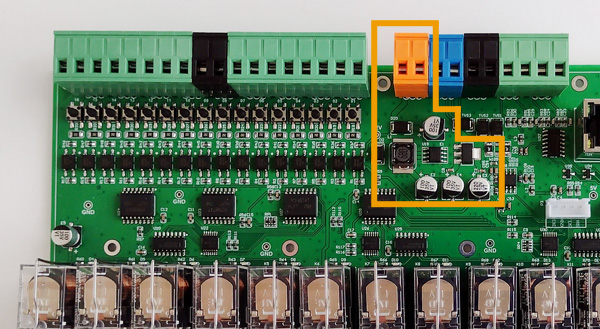
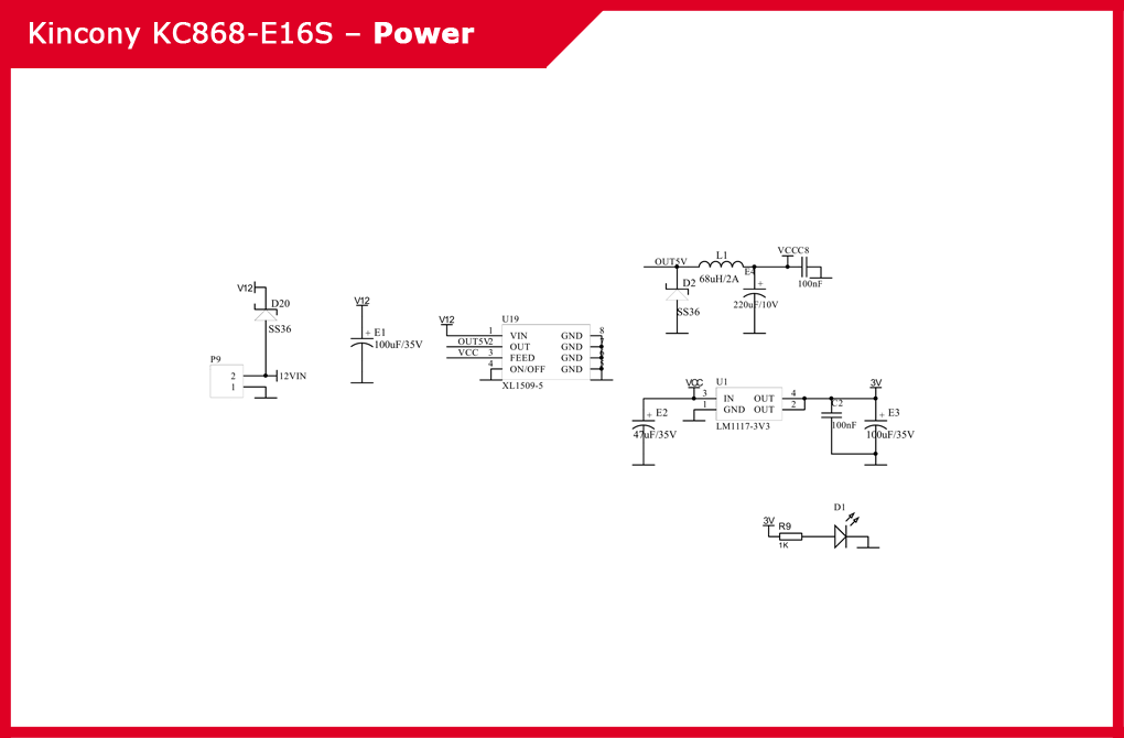
The power supply is completely standard for the KC868 series: the chip of the step-down DC-DC converter XL1509-5 is used to form a voltage of 12 V and 5 V, and the linear controller LM117-3V3 is used to form a voltage of 3.3 V. The power connector +12 V and GND is orange colored. You need to carefully look at what and where you connect so as not to damage anything. Schematic diagram of the KC868-E16S power subsystem:
ESP32 Core
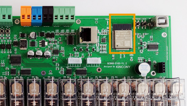
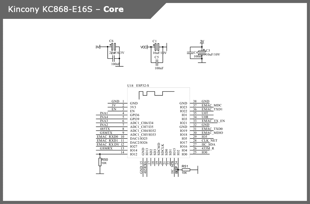
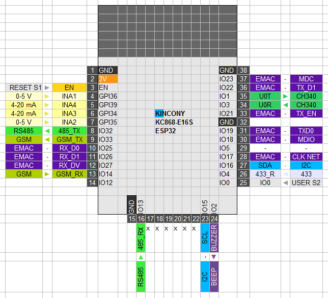
Below is the location on the board and the arrangement of the pins of the ESP-WROOM-32 module, at the end of the article I will give a more complete color layout KC868-E16S from the schematic diagram and the “official” pinout core of the ESP32 controller:
USB/CH340
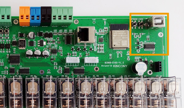
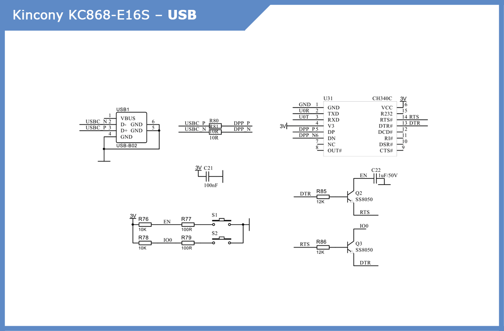
Subsystem for connecting to your computer and programming controllers. A full-size USB connector is used here. The following are CH340C and two buttons – “RESET” and “USER” (“DOWNLOAD”). Schematic diagram of the USB/CH340 controller subsystem:
Digital Inputs (DI)
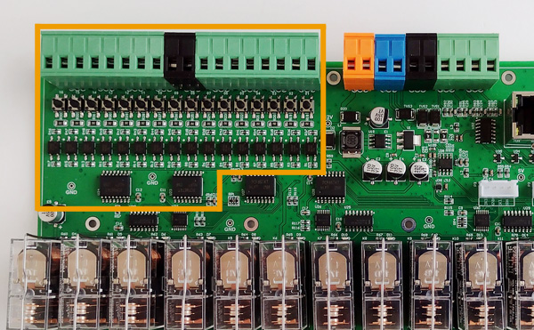
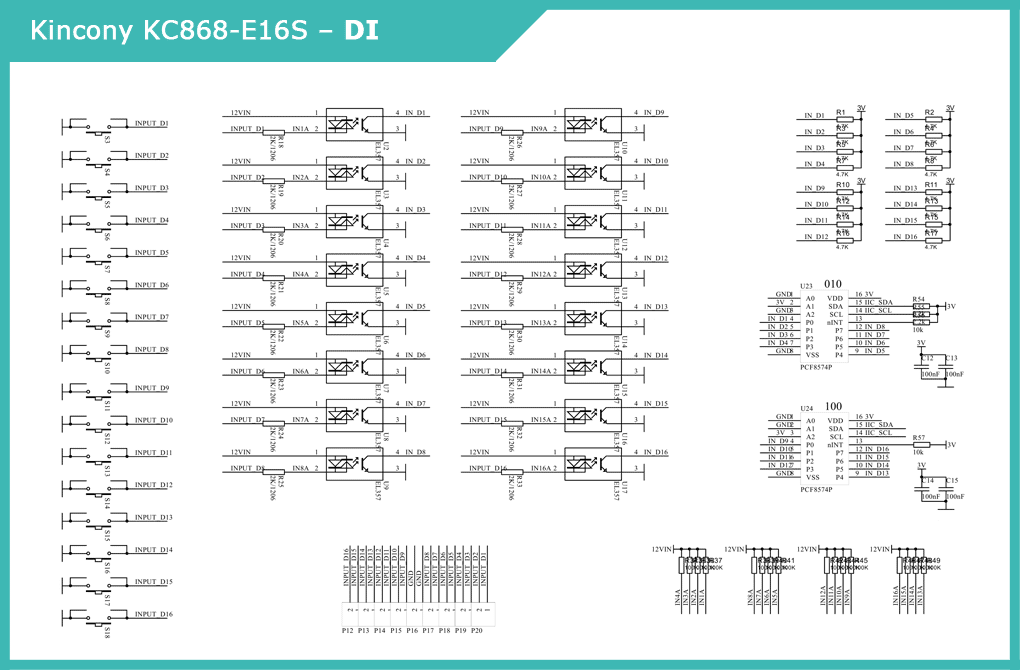
The KC868-E16S has 16 digital opto insulated inputs with a optocouplers EL357. ESP32 uses 2 digital I/O Extenders with I2C pcf8574P interface. On the board there are buttons for testing the inputs, which increases the convenience of using the controller. Schematic diagram of the digital input subsystem:
Analog Inputs (AI)
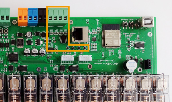
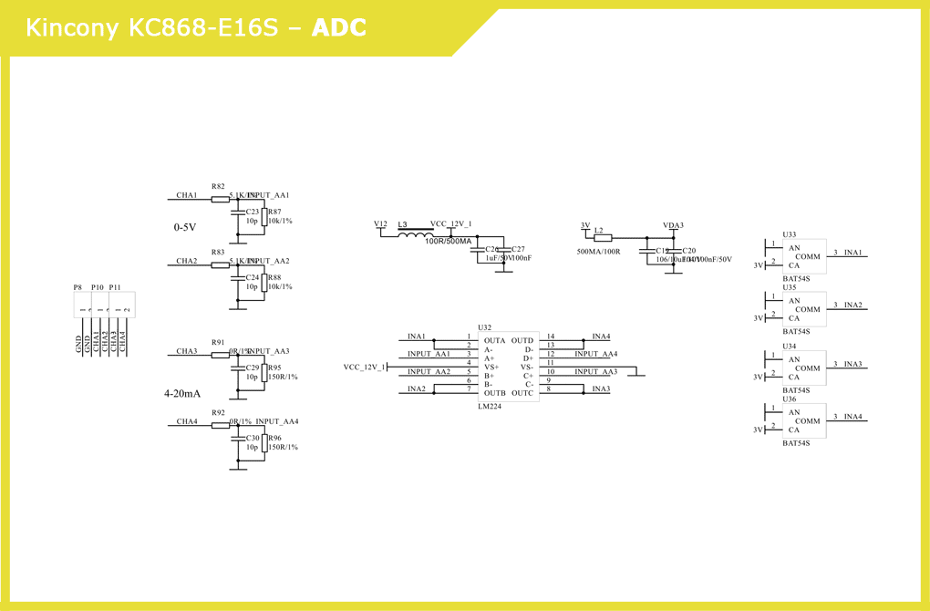
The KC868-E16S has 2 analog inputs of 0-5 V and 2 inputs of 4–20 mA. The signals are generated by input stages, a quadruple LM224 operational amplifier and BAT54S Schottky diodes. Immediately a voltage is formed VCC_12V_1. Schematic diagram of the analogue input subsystem:
Relays
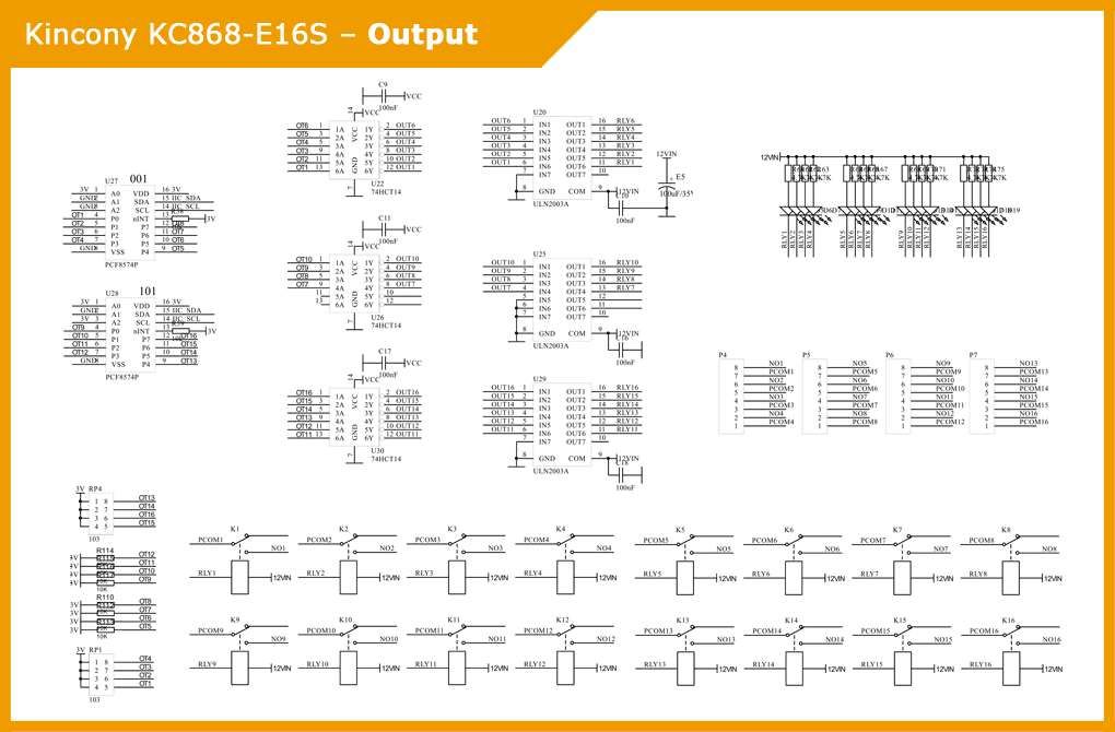
The 16 relays service 3 74HCT14 chips with Inverting Schmitt triggers and 3 ULN2003A chips with Darlington transistor arrays. On the board there are indicator LEDs that signal the current state of the relay. Interaction with the ESP32 microcontroller is carried out using two digital input/output expanders with the I2C interface PCF8574P. Relays have 2 contacts (NO and COM). Diagram of the relay subsystem circuit:
Buzzer
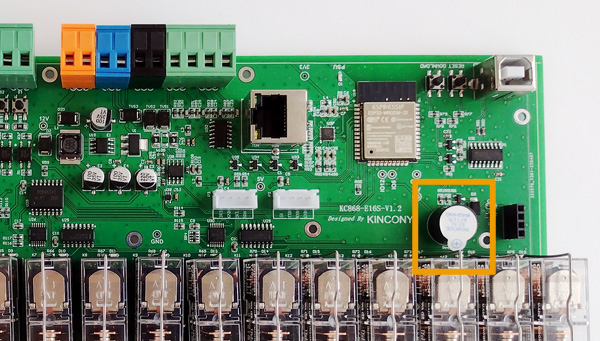
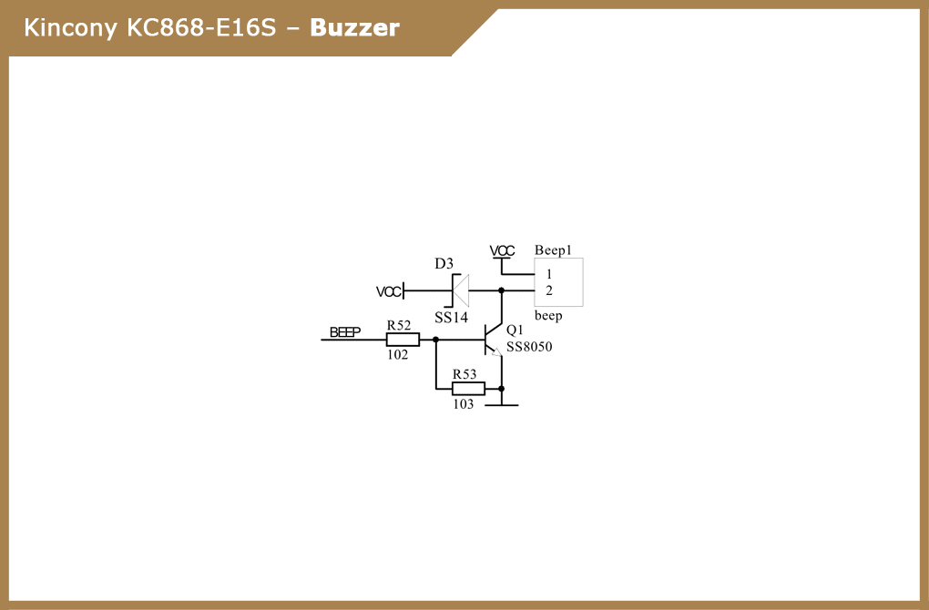
On the board there is a piezo ceramic buzzer, which is very good: if something goes wrong, you can inform the user about it. Beeps can also inform about various events within the system. Schematic diagram of the buzzer:
Receiver 433 MHz
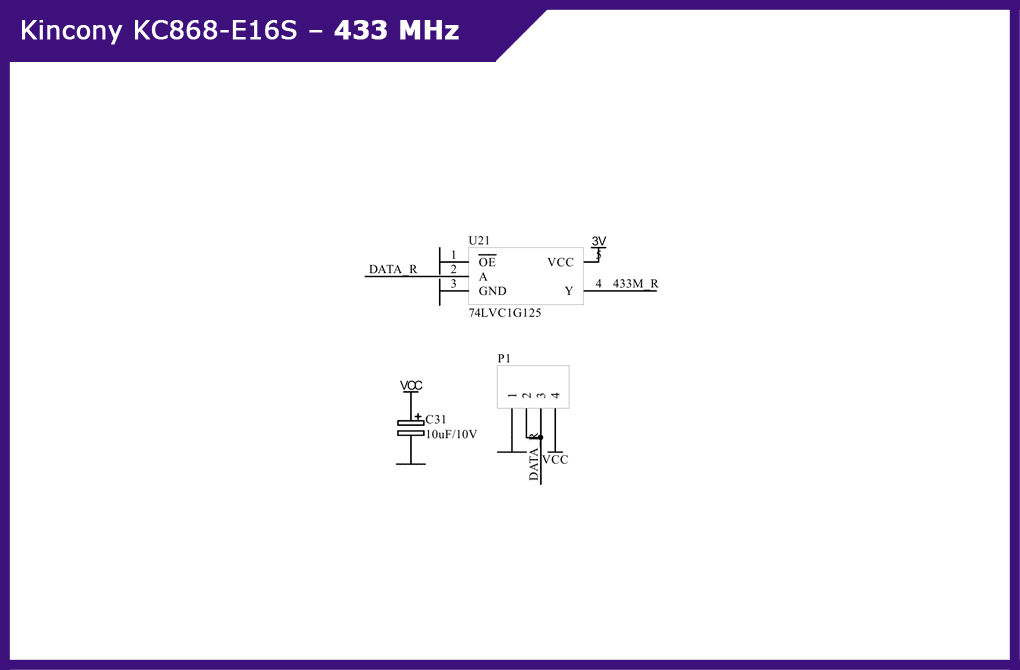
Here again we see one connector for connecting the 433 MHz receiving module. Although, in my opinion, it would be more logical either to leave both the receiver and the transmitter, or to completely abandon the support for wireless communication 433 MHz. Schematic diagram of the subsystem for connecting the wireless receiver to 433 MHz:
Ethernet
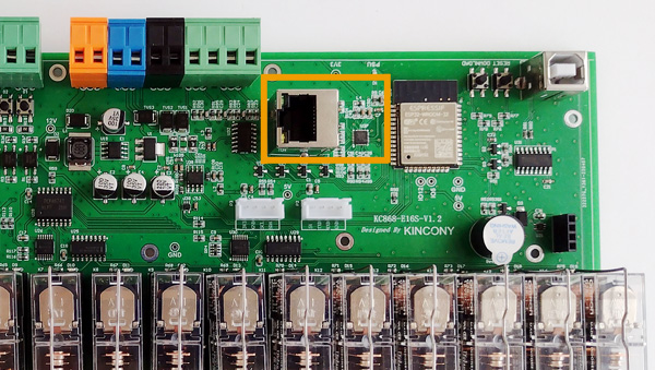
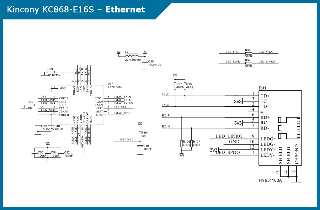
Ethernet interface with vertical connector. Obviously, so no one doubts the professionalism and coldness of KC868-E16S. Schematic diagram of the Ethernet interface subsystem:
RS485
RS485 interface in the implementation of max13487EESA driver chips and 74LVC1G125 buffers – takes up little space on the board and adds a lot of opportunities for the implementation of various automation projects.
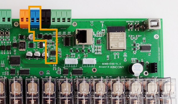
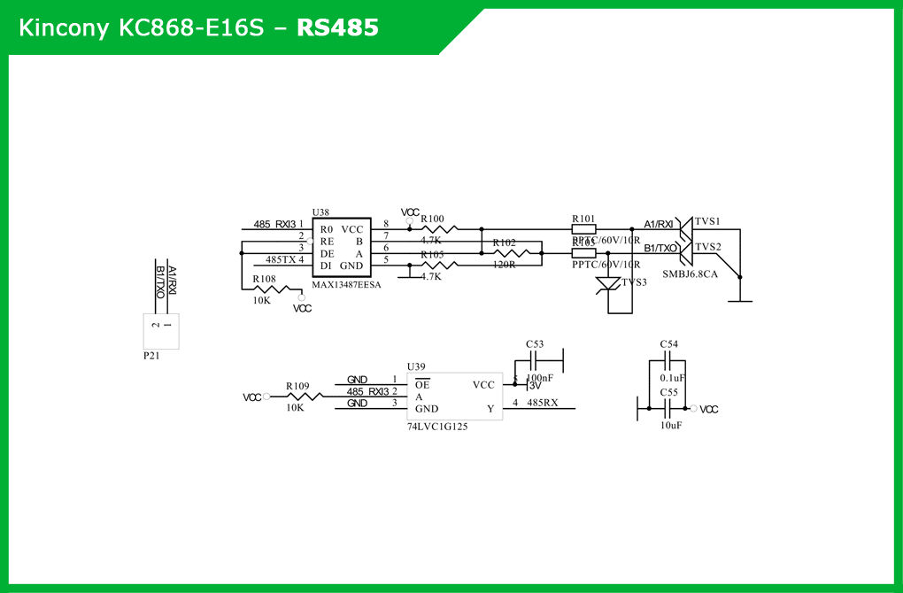
I2C
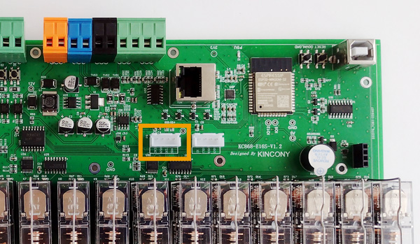
A separate I2C connector allows you to connect all additional components compatible with I2C (for example, the display) to the controller and significantly expand the functionality of the controller.

Serial port
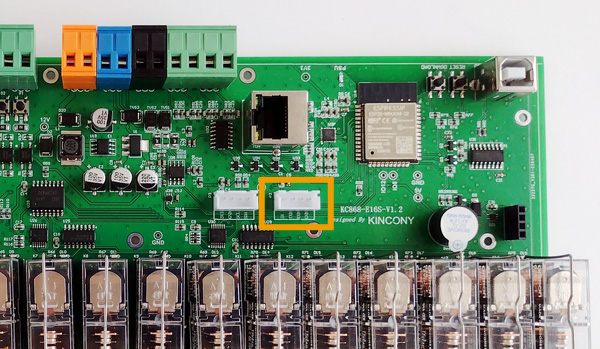
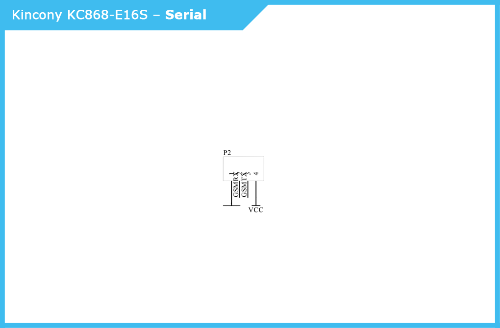
Multifunctional serial connector, HMI, GSM, etc. Under these sophisticated markings hides a serial interface to which you can connect various accessories (RX / TX).
Pin Layout (Pinout
A promised detailed view of the KC868-E16S controller color pins that gives a comprehensive idea of what and how it is related to the ESP-WROOM-32 on the board.
Connection Diagram
Conclusion
If your automation task fits into the performance characteristics of KC868-E16S, then this controller will be a good solution for the implementation of your project. As in any other device, you can find flaws in the KC868-E16S, but in general I like this controller and would gladly carry out some project on it (which I will occasionally do).
