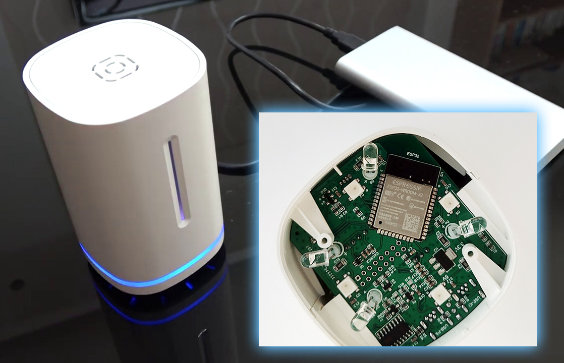
Today we will move a little away from studying of ‘serious’ controllers as the KC868 series (KC868-A4 [https://www.kincony.com/kc868-a4-hardware-design-details.html], or KC868-A8 [https://www.kincony.com/kc868-a8-hardware-design-details.html]) and let’s deal with a completely frivolous (at first glance) Kincony KC868-Uair controller. KC868-Uair is a kind of “unknown little animal with light bulbs”, with which it is not clear what needs to be done at all – whether it is a weather station, or an infrared (IR) control device for household equipment, or a smart home hub, or something else.
As a result of the analysis and surgical study of the KC868-Uair using a soldering iron, it turned out that it most of all resembles a universal wireless (Wi-Fi, Bluetooth) base for “light” home automation with the ability to add support for nRF24, LoRa and other wireless interfaces, which makes the device extremely interesting and potentially very useful in the household.
A nice appearance, the presence of a full-color event indication, a built-in piezoelectric buzzer, support for 433 MHz RF wireless communication, the ability to connect a display and the presence of free space inside the case for adding our own expansion boards make the KC868-Uair a device that we, as creative geeks, we can’t skip.
Kincony KC868-Uair
We will start, according to tradition, by finding out what the KC868-Uair consists of and what functional blocks it has on board. This is, of course, the core on ESP32 (ESP-WROOM-32) with all its inherent features (Wi-Fi, Bluetooth, two cores, 4 MB of built-in EEPROM memory, etc.), as well as:
– Built-in temperature sensor DS18B20
– Infrared (IR) receiver and transmitter
– 433 MHz receiver/transmitter modules
– Piezoceramic buzzer (Buzzer)
– 2 blocks (1/4 pcs.) indicator LEDs WS2812
– Connector for connecting external I2C sensors and IR LED
– Internal pinout with 12 free GPIOs
– Mini-USB connector for power/computer connection
As you can see from the list above, the KC868-Uair is already quite a functional device out of the box and allows you to measure the temperature both at the Uair installation site and at a distance using a remote sensor, control household equipment via an IR channel, receive data and send commands to wireless devices 433 MHz, sound current events using Buzzer, indicate various system states using two (independent) lines of full-color WS2812 LEDs, connect remote sensors to the device, etc. And given that all this is controlled by a fairly powerful microcontroller ESP32 with Wi-Fi and Bluetooth on board, it is obvious that the “bottleneck” here will not be the capabilities of the device, but your imagination and programming skills.
That’s not all, the KC868-Uair has an internal pinout with 12 free ESP32 pins (finally!) and 70 percent free space in the case, which allows you to equip your Smart Station (let’s call it that) with whatever you need. additional components. And since the list of additional components that can be connected to the KC868-Uair in this way is almost endless, your options for upgrading the KC868-Uair are almost endless.
Looking ahead a bit, I’ll say that with a little work with a soldering iron (and in some cases without a soldering iron), you can access the SPI and I2C interface pins on the controller board, which allows you to equip the KC868-Uair with a display, wireless nRF24 or LoRa interfaces and create a truly powerful IoT device in a compact and nice case KC868-Uair.
Web interface
I want to say about the web interface. ESP32 is a fairly powerful microcontroller that allows you to serve a full-fledged (in the sense of using HTML, CSS, Ajax, Websocket, etc.) web interface. Therefore, our Smart Station on KC868-Uair can have a luxurious interface with dozens of web pages, an interactive interface for managing connected equipment and settings, can provide colorful analytics and graphs, etc.
That is, to be a self-sufficient device that does not need any Linux Raspberry Pi control computers or MQTT brokers (compare the price and power consumption of ESP32 and Raspberry Pi). The KC868-Uair can be a master controller itself with its own user-friendly web interface. Of course, for this, the appropriate firmware must be installed on the KC868-Uair, which supports all these features – it all works fine for me on the test version of AMS for the KC868-Uair, and you will need to look for the appropriate firmware or write the software yourself.
NRF24 and LoRa
Now let’s imagine: in the face of KC868-Uair, we already have a fairly functional device in itself, which can also receive data and send commands to wireless devices at 433 MHz. (Already not bad.) But what happens if we add the ability to work on nRF24 and / or LoRa to our Smart-station? – the capabilities of our station will increase exponentially and our modest-looking “cuckoo’s nest” will simply turn into a “ring of omnipotence” with dozens, if not hundreds, of connected wireless sensors and actuators.
Cool? It seems to me that it is very, especially for such a modest-looking device as the KC868-Uair. What and how to do to equip the KC868-Uair with wireless nRF24 and/or LoRa support
I will tell you the connections in the next article, there I will also give detailed pinouts, soldering instructions, links to the necessary libraries, code examples, etc.
Power supply
Power and communication with the KC868-Uair is carried out using the Mini-USB connector. Accordingly, this is 5 volts from any high-quality USB connector on a computer or mini-power supply. In my opinion, this is a simple and convenient solution – connecting the KC868-Uair is no problem. True, problems may arise if you want to equip the KC868-Uair with some kind of higher energy consumer additional equipment – but this is a specific issue and we will not dwell on it here.
The special charm of this solution is the ability to power the KC868-Uair from any power bank and turn on your Smart-station right in the field. And what? They turned on the station from the power bank and scattered it around “field” a dozen of the sensors you need – got a mobile “smart home”.
Appearance and body
As I mentioned above, the Kincony KC868-Uair has a simple, but at the same time quite nice and modern designed housing.
The indication is also made competently and functionally – there is a horizontal belt (4 independent full-color LEDs WS2812) and a vertical band (1 LED WS2812) – this combination allows you to visually (and beautifully) look good (and beautiful).
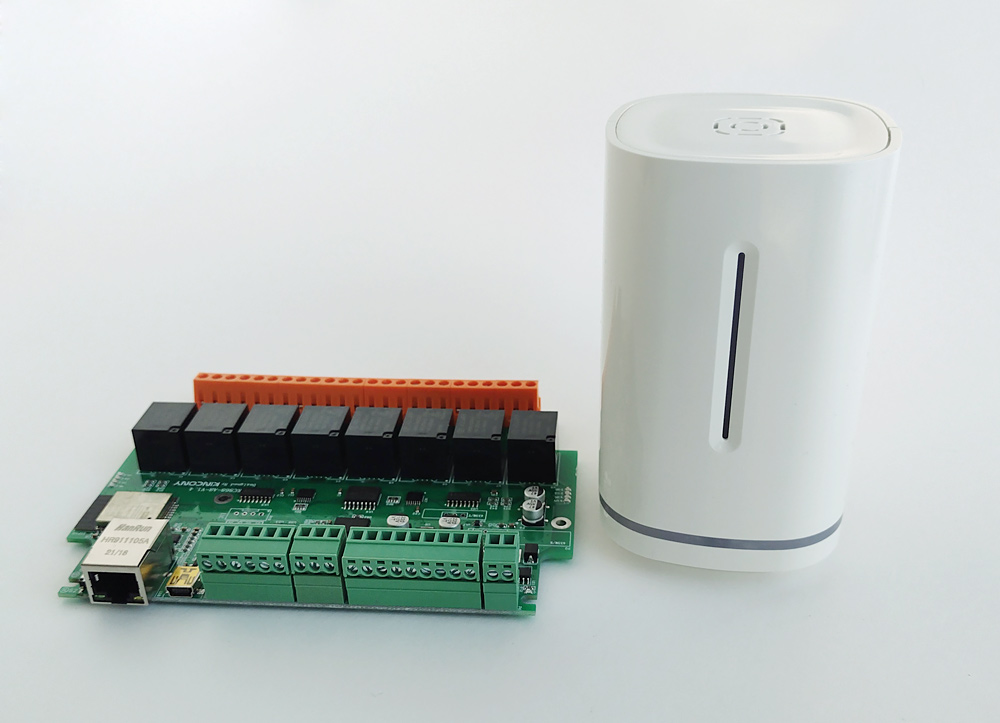
Below is a photo of the KC868-Uair compared to the KC868-A8 controller you already know.
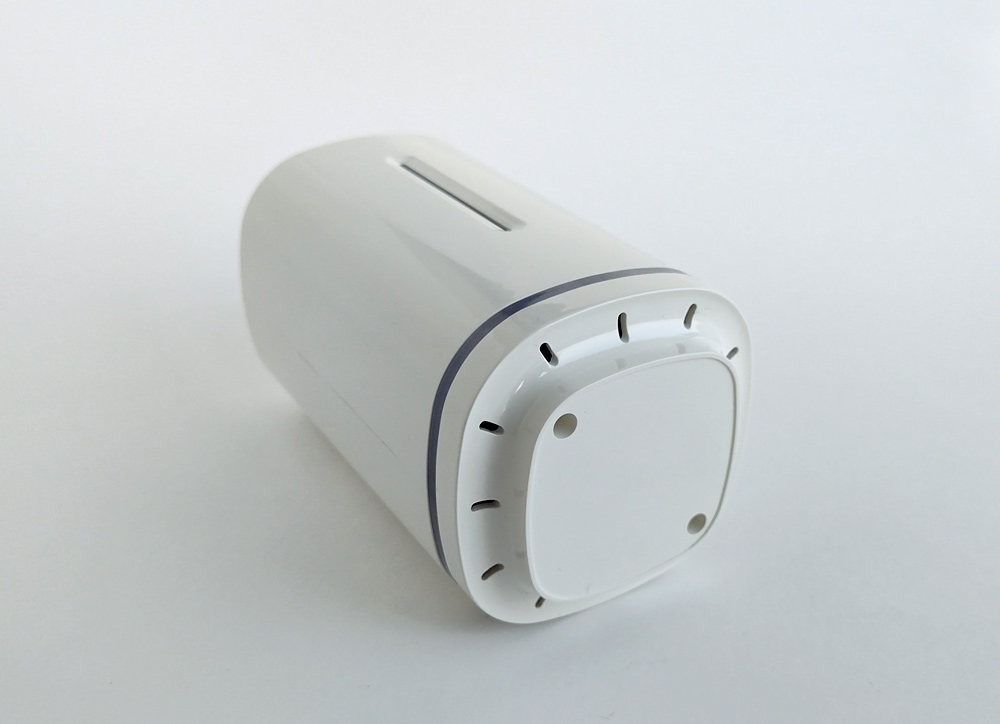
Bottom view: Two holes for mounting screws and ventilation holes for ambient air intake. Everything is done competently enough – the air can pass freely through the holes in the lower and upper part of the body. The body itself stands on a small hill in appearance
“Legs” (which allows air to pass freely through the holes). If necessary, additional holes can be made in the housing for better air circulation.
Kincony engineers have installed two mini USB connectors, one for power and the other for connecting external sensors. There are no markings on the case that are used for what. I guess that will cause confusion and problems could arise.
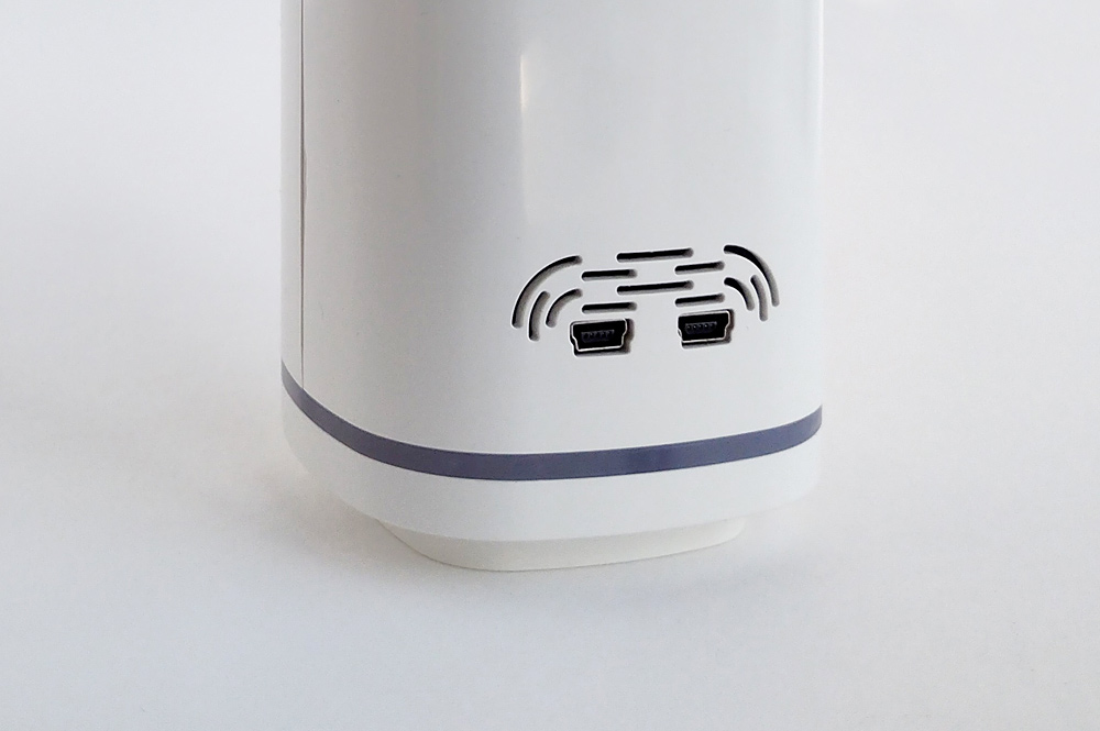
KC868-Uair – USB ports
More about the case
The KC868-Uair case, besides being beautiful, is also quite functional. Below is a photo of the case in disassembled condition. Note the 3 pairs of guides forming 3 “Floor” for the installation of printed circuit boards. One floor is occupied by the KC868-Uair board, and the other 2 remain completely at our disposal – you can supplement your Smart-station with two more boards with the components you need.
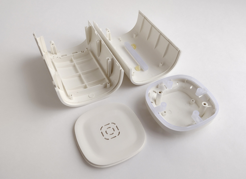
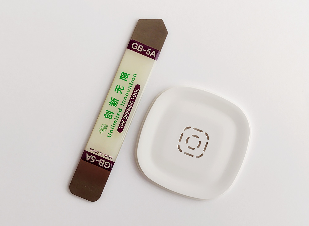
Here it is necessary to tell about one “ambush” which waits for each owner KC868-Uair – externally the case looks very well, but to disassemble it not so simply, at first moment it seems that it is impossible at all. In fact, this is not the case – the body is fastened with 3 latches from each edge (they can be seen in the photo). I was able to open and disassemble the body KC868-Uair only with the help of a special magical Chinese instrument.
The electronic board
The KC868-Uair board installed inside the case. This is the bottom view, with the bottom cover removed and the light guide strip for four WS2812s. You can see the mounting rods for screws, guides for mounting the printed circuit board and gaps for air circulation inside the case.
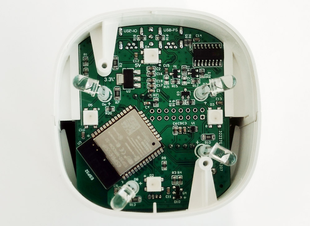
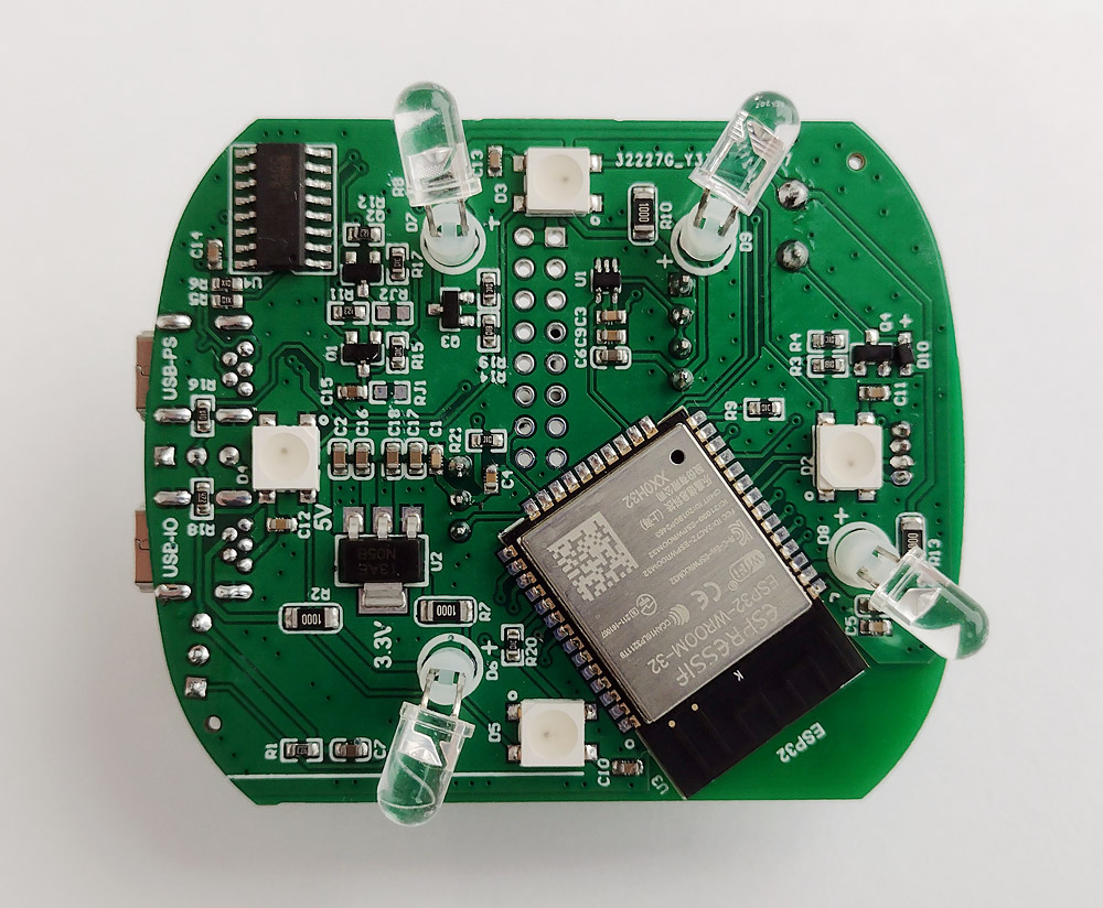
The board removed from the case, the side of the ESP32 and most of the installed electronic components.
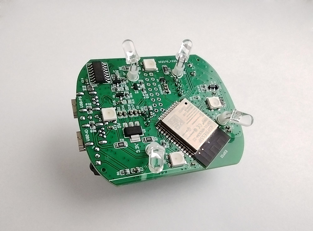
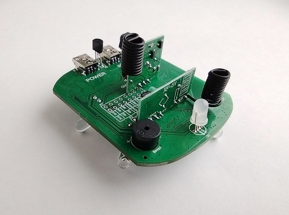
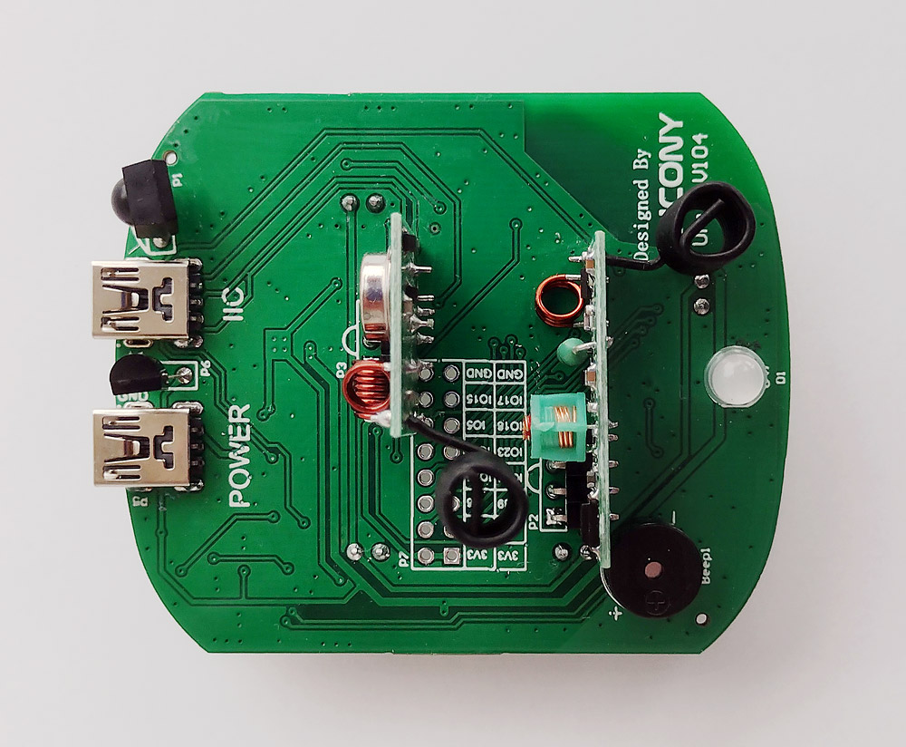
And a view of the board from the back side, where 433 MHz wireless modules, a buzzer, a temperature sensor, a WS2812 LED and an IR receiver are installed. The manufacturer kindly supplied the wireless modules with antennas.
Schematics of the Kincony KC868-Uair board
Now let’s move on to the analysis of the circuitry of the Kincony KC868-Uair board. Top view and close-up of installed components.
Bottom view. Behind the antenna is a connector with free GPIO pins for connection. As you can see, in the initial state, the pins of the connector are not soldered and if you want to seriously work with this controller, you will have to remember your soldering skills and unsolder them.
Here we meet with another jamb of Kincony engineers – the transmitter module is soldered in such a way that without dismantling it it is impossible to unsolder the connector with free GPIOs. I had to solder the transmitter module and only after that I was able to solder the missing pins.
While I was doing soldering, I had a question: why solder this module at all, when instead of it you can solder a 3-pin connector and insert a wireless module into it when you really need it?
I did just that and now I have one more free GPIO at my disposal. You can also put the 433 MHz receiver module on a 4-pin connector instead of soldering.
Power supply
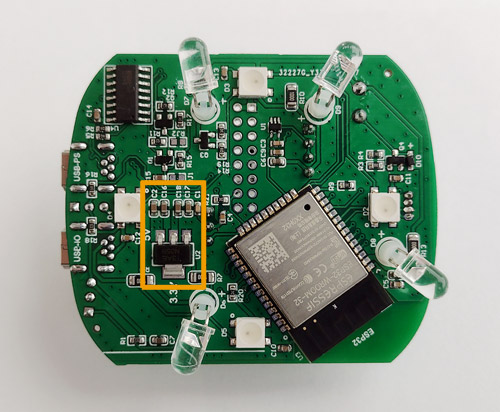
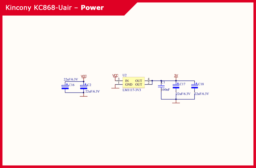
The power supply subsystem of the Kincony KC868-Uair is extremely simple, it uses only a linear regulator LM117-3V3 with the appropriate elements to generate a voltage of 3.3V.
Schematic diagram of the controller power subsystem:
ESP32 core
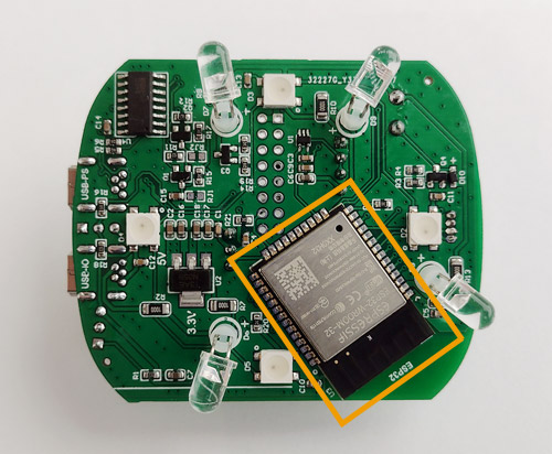
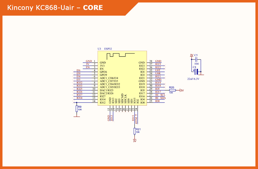
The ESP-WROOM-32 module, which we have already mentioned earlier, is used as the core of the Kincony KC868-Uair controller. This functional block includes 2 more filter capacitor located in close proximity to the ESP32.
Schematic diagram and pinout of the core (ESP32) of the controller:
USB/CH340
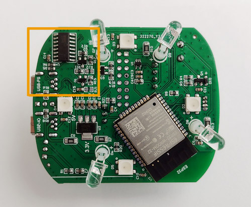
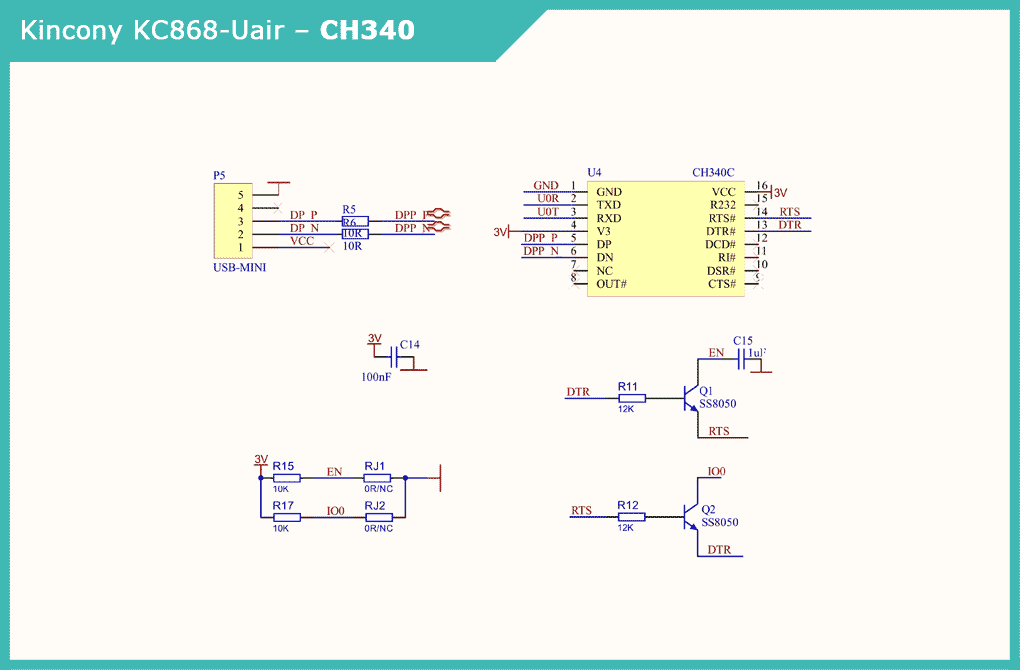
For connecting to a computer, programming and uploading firmware to the ESP32, the board has a Mini-USB connector and a CH340C USB / Serial converter chip, as well as the corresponding harness for automating sketch loading. The “RESET” and “USER” buttons are absent, but if necessary, they can be added (by uncovering and use the soldering iron).
Schematic diagram of the subsystem USB / CH340 controller:
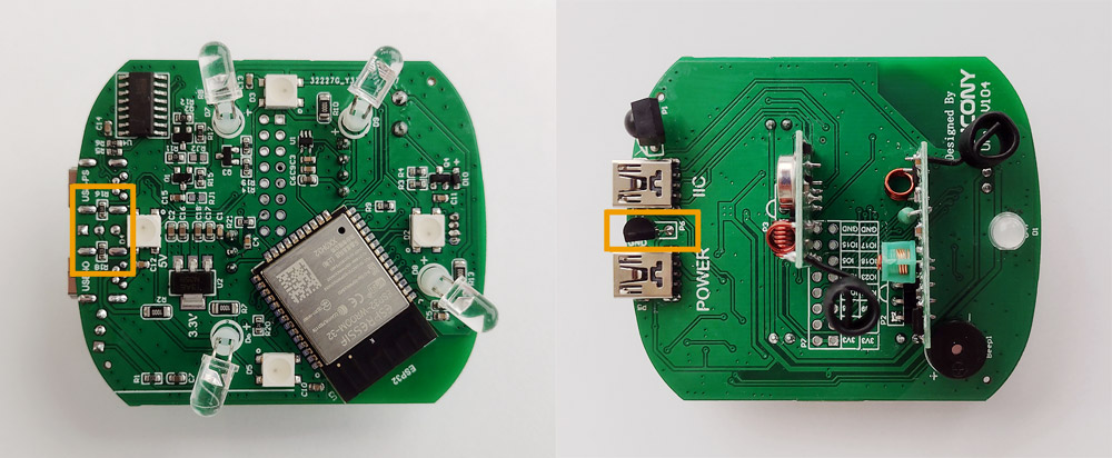
Temperature sensor
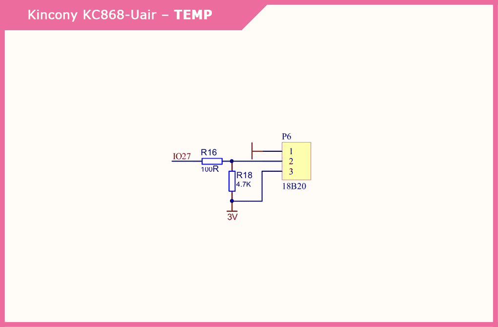
The DS18B20 temperature sensor is soldered to the board and will most likely measure the temperature in the case, and not the ambient air temperature. Here you need to deal with calibration and the introduction of the appropriate correction factor or use an external (remote) temperature sensor. Various creative options are also possible, such as desoldering the sensor and soldering a network of several sensors instead, and other similar delights.
Schematic diagram of the subsystem for connecting temperature and humidity sensors:
Buzzer
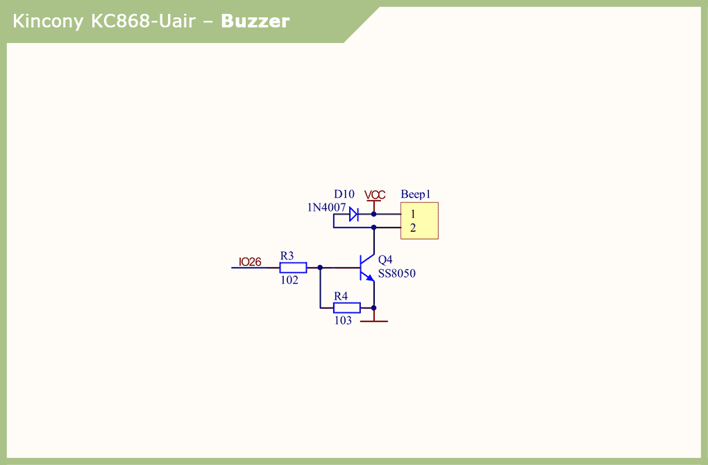
The scheme of the piezoelectric buzzer is extremely simple and does not require comments, I will note only that the presence of the sound buzzer is very useful, because you can easily notify users of various alert.
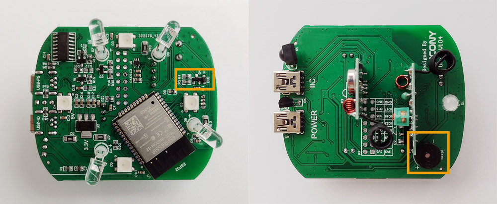
Schematic diagram of the piezoelectric buzzer connection:
Infrared receiver / transmitter
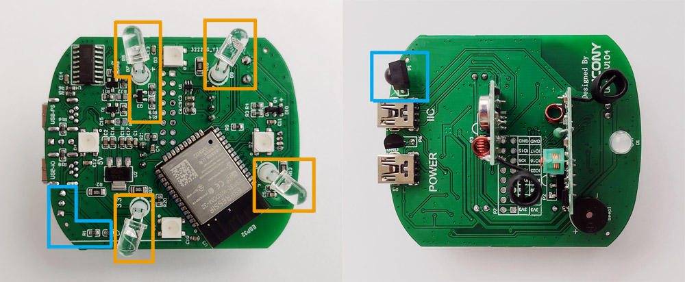
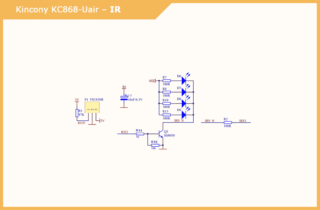
The Kincony KC868-Uair board is equipped with an infrared receiver and emitter. As an IR receiver, a VS1838B sensor with a harness is used. And 4 emitting IR diodes are used as emitters.
The installation scheme of the diodes is questionable – they are directed downwards and apparently designed to work through the lower ventilation holes (with reflection from the KC868-Uair installation plane) and / or through a light guide (encircling a translucent circuit) – how effective such a solution is yet to be found out by setting the appropriate experiments.
The diagram also shows that there is an output for an external IR emitting diode on the corresponding Mini-USB connector.
Schematic diagram of the infrared receiver and transmitter subsystem:
RF 433 MHz modules
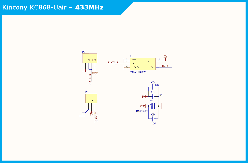
The buffer element 74LVC1G125 is used to form and supply the controller with an input signal from a 433 MHz receiver, and the output signal to a 433 MHz transmitter is fed directly.
It must be said here that far from everyone and far from always needs wireless communication at 433 MHz, so you can simply “put” these modules on the connectors (I already mentioned this above) and use the freed GPIOs to connect the equipment you need.
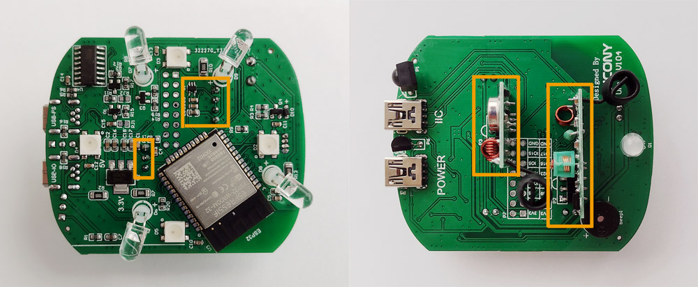
Schematic diagram of the subsystem for connecting wireless modules at 433 MHz:
Indicator LED’s – WS2812
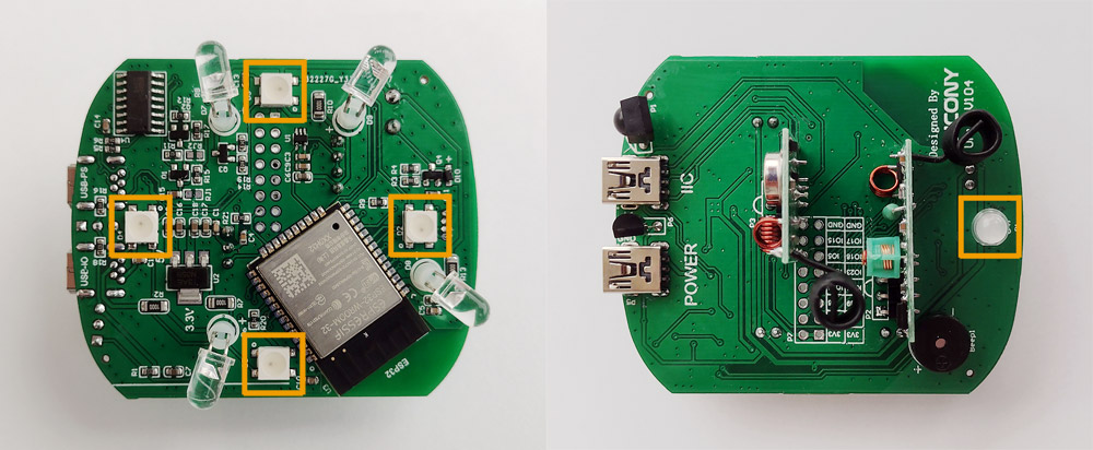
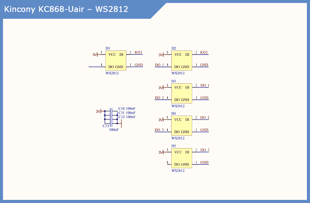
As you remember, Kincony KC868-Uair is equipped with two indicator lines on “smart” WS2812 LEDs. The location of the rulers and their device is clearly visible in the illustrations below. On one side of the board there are 4 “encircling” LEDs, and on the other – 1 to highlight the vertical bar.
Each LED can be accessed individually and set to any color, and dynamic indication with various effects is also available. Of the jambs, it was noticed that a separate “vertical” LED does not work correctly – it has the red wiring mixed up and green channel, but this can be easily compensated in the code.
Schematic diagram of the display subsystem on the WS2812:
Interfaces
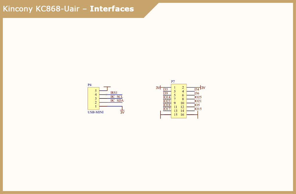
The Kincony KC868-Uair has an I2C interface on an external Mini-USB connector, but if you want, you can work a little with a soldering iron and get access to it inside the controller. Also in the photo and schematic diagram you can see the pinout of the connector with 12 free GPIOs,”ground” and a voltage of 3.3 V to which you can connect your additional equipment and components.
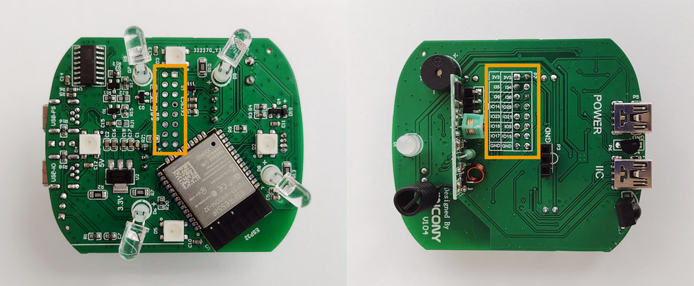
Schematic diagram of connectors:
Conclusion
In general, we can say that the Kincony KC868-Uair is a very interesting device, especially if you have imagination, you own a soldering iron and have microcontroller programming skills. In this case, you can spend some time and have a lot of fun making your version of the “omnipotence ring” out of this “cuckoo’s nest”. And in the next article, we will figure out how to connect wireless nRF24 / LoRa communication modules to the KC868-Uair and learn how to program them – and then the IoT cuckoo will settle in our cozy nest.


