Smart Lighting Control System Implementation Case
This Case will show us how to control the lighting with the device KC868-H8, and what kind of controlling ways.
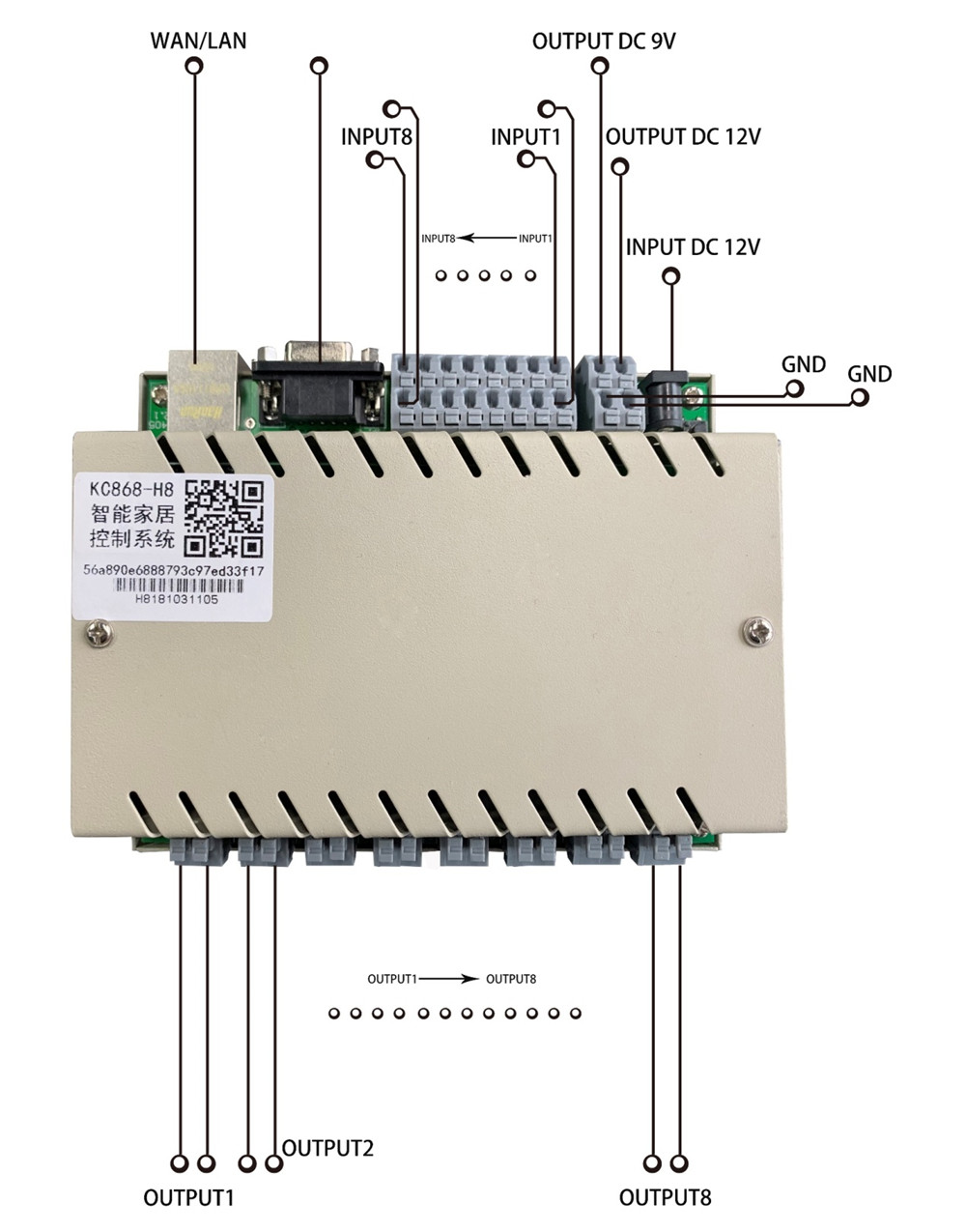
Firstly, let us have a check the main interfaces of the device:
- 12V power supply port
- External power supply outlet
- Network port
- RS232 serial port
- 8-channel relay output port
- 8-channel signal input port.
The maximum load for each channel relay output can be 250V/10A and each output is dry contact signal.
(See below Picture)
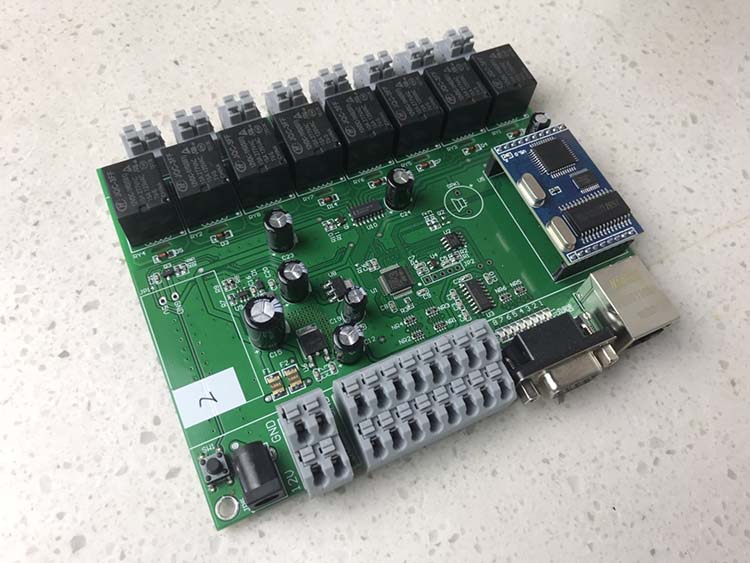
And below Picture is the inside of the device KC868-H8
Next, we will show how to connect the device. Please have a look at the below Picture.
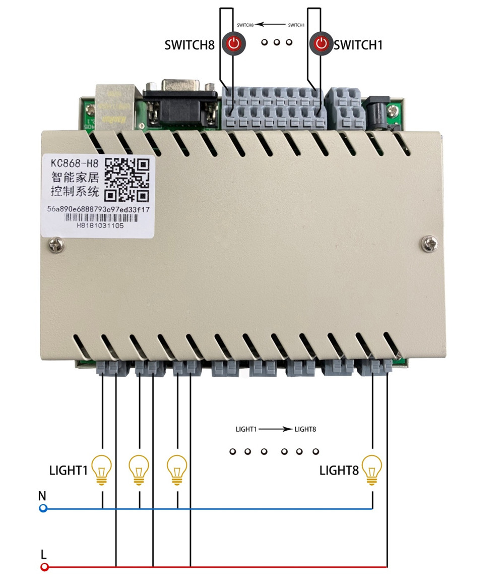
From the picture, we can see there are switches and lamps connecting to the device. And they are 8 switches controlling the related 8 lamps. Please pay attention that the connecting ports for switches are “up” and “down” and the connecting ports for lamps are “left” and “right”.
After finishing the connecting as the picture, we can control the lamps directly by the switches.
When connecting to the lamps, please note the relay is 10A/AC 250V, which means the maximum power of the lamp could be 2500W. However, to considering the safety, please keep the power of the lamp below 1800W. And normally, it is also enough for most using status.
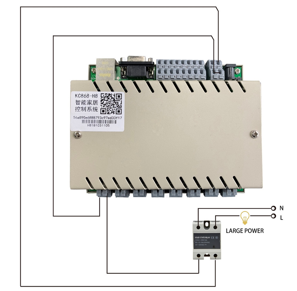
However, if the actual power of required lamps is exceeding the rated power range, we can use the solid-state relay to achieve the power expansion. Normally, there are 20A, 30A, or 60A even more big solid-state relays. We can choose the related article to match the requirement.
Hereby, we show you one picture of the solid-state relay and the wire connecting as below Picture;
The input of the relay is 3V-32V/DC and the output is 24-480V/AC. It can solve the problem of using for big rated power requirement.
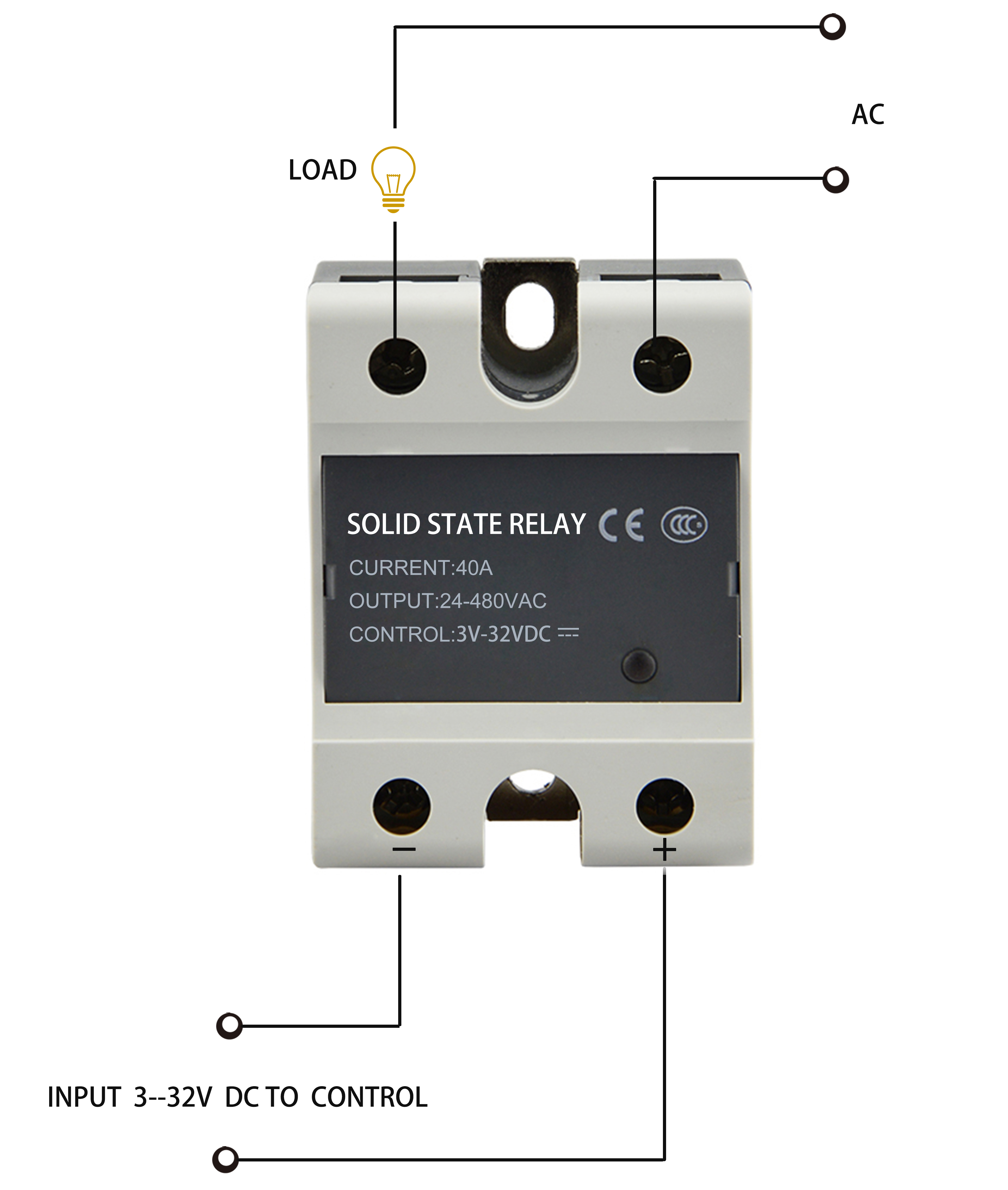
Following, we show how to connect the solid state relay with the device of KC868-H8 as below picture; from the picture, we can see the rated power can be much bigger accordingly.
We know the device has 8 input ports, which can be connected to 8 switches. As normally, the device is remote controlled by the smart system.
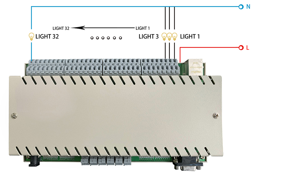
If you want to connect more equipments, please choose KC868-H32 controller, which is the corresponding wiring diagram.
But when the remote controlling is not available because of some un-expected reasons, we can also control the device locally by the switches.
Hereby, we show some switches pictures, and please make note that the switches are self-return buttons.
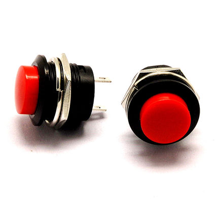
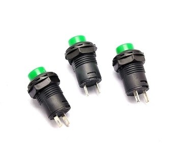
There are different colors and varied styles self-return switch buttons available, you can choose the one you like.
What’s self-return switch button?
As the meaning of the name, when pressing the button, the switch is put through, when un-pressing the button, the switch will be cut off. As long as the condition is similar like this, we call them self-return switch button.
And the connecting of the switches is very simple; just connect the positive pole and negative pole into the input ports of the device.
Now, we use the Kincony smart home model to connect the wires and display the controlling. We connect the lamps with the output ports of the device KC868-H8; meanwhile, we get 8 self-return switch buttons connected to the input ports of the device. (See below pictures)
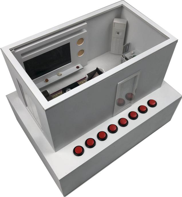
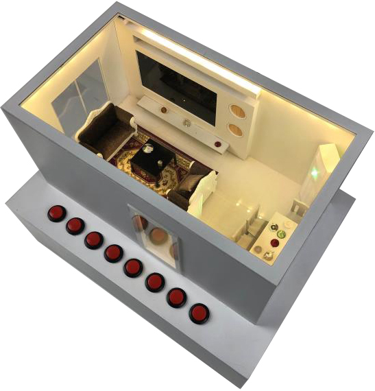
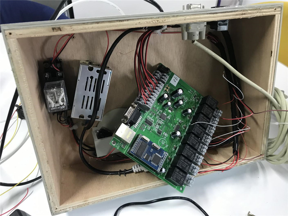
After finishing the wires connecting, we can try to control the smart house model with below 4 models:
- PC remote controlling
- PC local controlling
- Mobile phone APP remote controlling
- Switch button local controlling
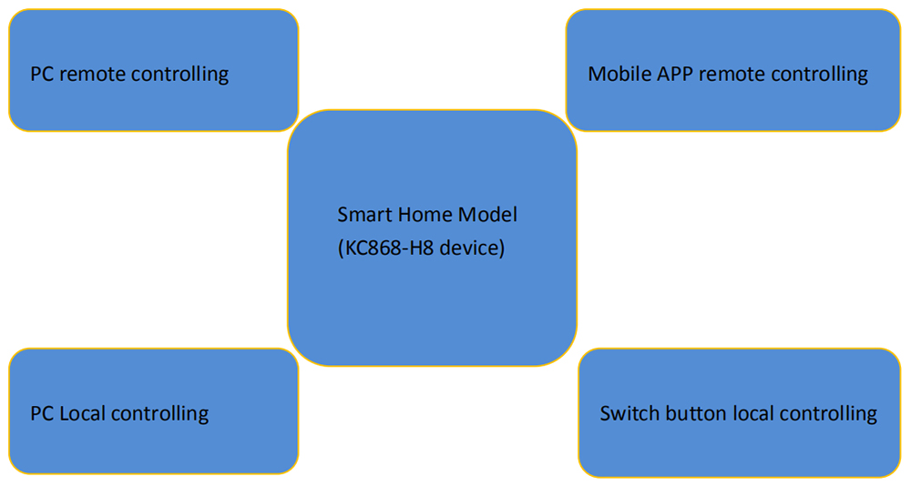
For these 4 controlling models, the PC application software is based on the previous controlling communication protocol, which is including the functions of controlling through local network mode and remote mode, as well as the function of reading the switch state of the relay output.
At the end of the article, we will provide the links to download the source code for you to learn and redevelop. You can develop different forms and styles of applications suitable for different industries.
- PC remote controlling
First, download the PC application software of the KC868-H8 device from the link:
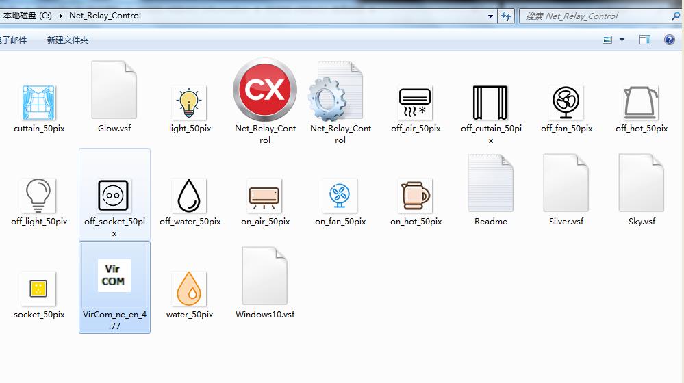
Please store the unzipped file in the root directory of the C disk when the first download. As shown in the below picture
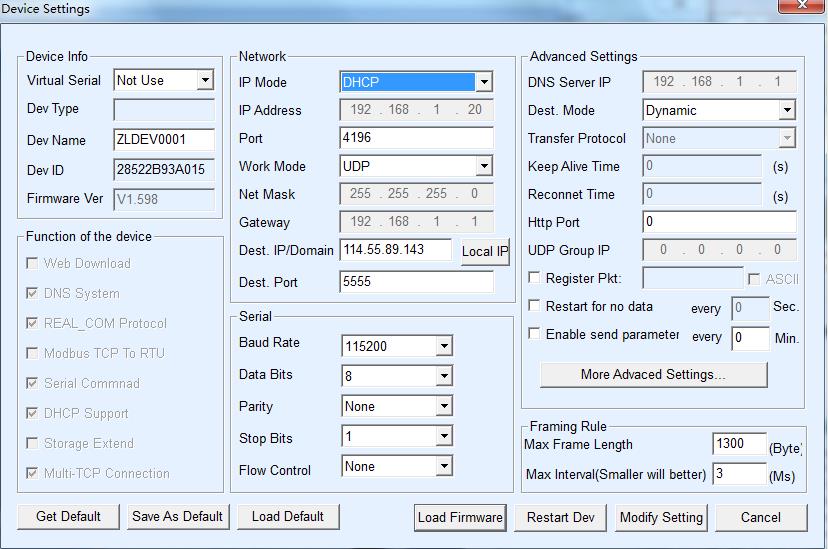
Second, open the network configuration tool of “vircom_ne-en4.77” program, modify the “work mode” into “UDP mode”, and set the “destination IP and domain name” into our cloud server address”sdk.hificat.com”, the “destination port” into “5555”. Then”IP mode” recommendation to be set to “DHCP”, which means the router DHCP dynamically allocates the IP address. Normally, the router opens the service of “DHCP dynamic assignment IP”, otherwise, we need to set the router to open it.
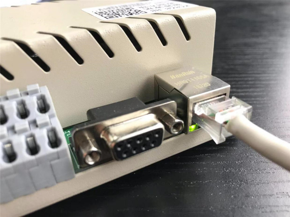
After finishing the network configuration, get the device power on, the device will be automatically connected to the internet. And the network light will become green when the connecting is successful.
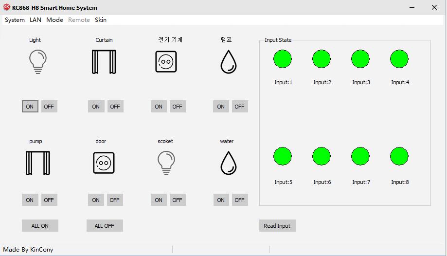
Then, we open the program of “net_relay_control.exe” to set configures the device’s parameters.
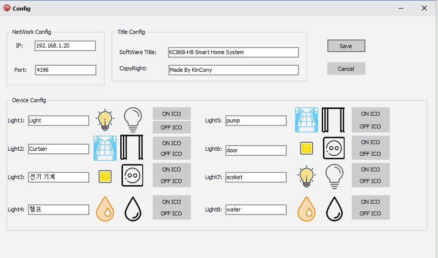
According to the device IP address parameters in the network configuration tool previously, we fill in the corresponding column. When the configuration information input is complete, we click the “save” button and close the software to reopen it, which make our configuration setting to take effect.
Then dropdown the “mode” menu, select “WAN” as below picture (it is LAN mode as default)
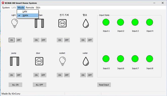
Next, we dropdown “Remote” menu to open the “config” window.

Click the “config”, as the below picture; we see that there are the text columns for 4 devices, which can be named and set. Because the main program interface shows a control icon for an 8-way device in a control box, then when we connect multiple control boxes at the same time, we need to make the switch choice of the control box. This is why we need to set the name of the control box. Note: the four control boxes configured here can be anywhere, not limited to the same LAN, as long as the control box can be connected to any place where the internet network can be connected, and can be used at home or abroad. If you have a control box, set up a message for one, two for two, and a few for information. When setup is complete, clicking the Save configuration button and shutting down the software before reopening will take effect.
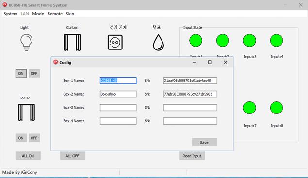
We just make two set devices for displaying, and you can see the below picture that two devices can be controlled now.
After setting up the basic information, we can control each device by clicking on the “on” and “off” button of each device, and the status of the device will be displayed by using a different color icon. Software interface below the “full open”, “full off” button, can open all the switches, and once off all the switches. Now that we can remotely control the lights from the computer, isn’t it very simple, in remote mode, to remember the most important “serial number” parameter, which is the only sign that distinguishes the device.
- PC local controlling
First, we need to use the Network configuration tool ”vircom” to set the device’s work Mode to TCP Server mode. Now, the device KC868-H8 is used as a smart home server role, and the computer as a client role. The control mode of the local network, that is, the device and the computer software realize the point-to-point communication control, and do not transit through the data of the cloud server. This way can be used only with the device and in the same LAN.
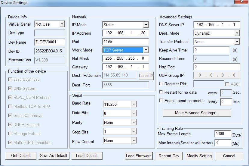
Then click the program “Net_relay_control” to open the main controlling window.

Open the controlling window as below, click the system button and choose config to open the “config” window
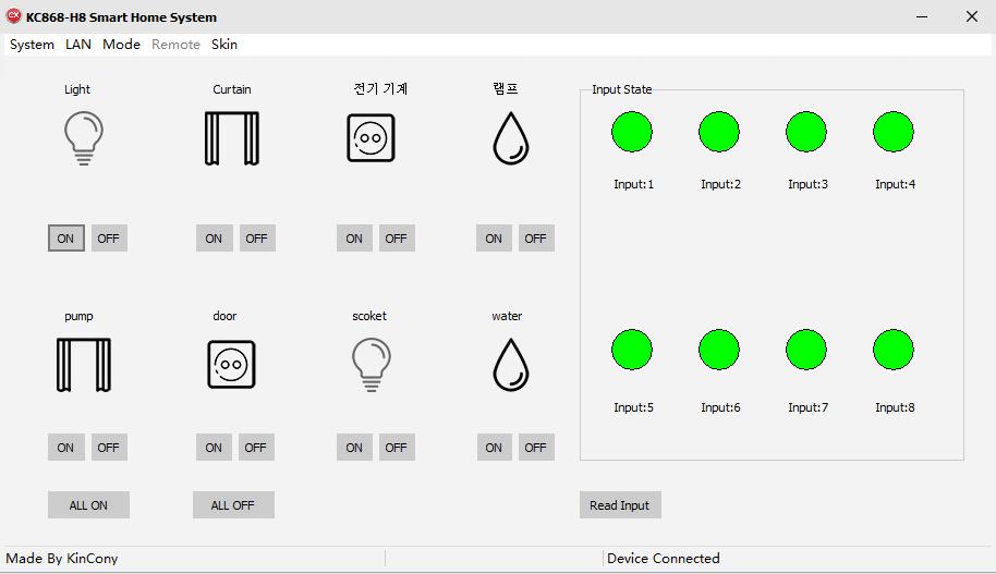
It is the “Config” window as below:
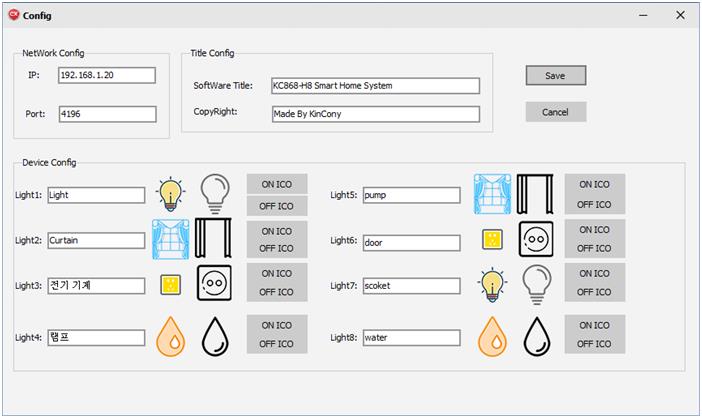
According to the device IP address parameters in the network configuration tool previously, we fill in the corresponding column. When the configuration information input is complete, we click the “save” button and close the software to reopen it, which make our configuration setting to take effect.
After that, we dropdown “LAN” button to click the “connect”, it will show “Device Connected” and “Connect OK!” at the bottom.
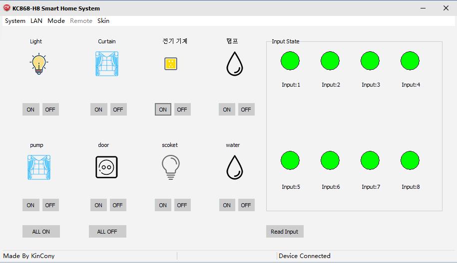
Then, dropdown “LAN” button again to click “Initialization”, it will show “Initialization completion”.
This setting is very important, please make sure to do this setting right.
Now, we can control the “on” and “off” button to open and close the applications .
- Mobile Phone APP Remote Controlling
Download Apple or Android smart control software app, via Crystal’s website to open the app, selection registration page, follow the prompts to register the phone number, and then log in. After registering for the first time, the system Wizard recommends adding “floor”, “Room”, and “add Host”, among other basic configuration actions. After that, you need to add a host operation to the app side of your phone, click “my-host management,” click “add,” click the “scan QR code” icon, scan the QR code of the kc868-h8 control box, and set a nickname for the device. Click add to complete host addition.
In “my”-“my device”-“not classified,” the icon that has just been added to the control box is displayed, the number at the bottom of the icon is the corresponding serial number, and the “room” is selected for the control box by clicking the icon. “device name” according to the actual situation to name, the device icon can choose its own, select the actual control box “room” location, and then click save.
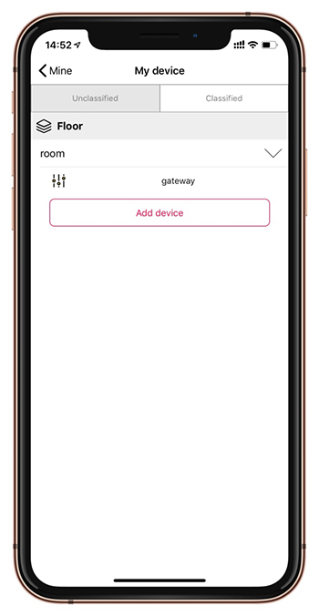
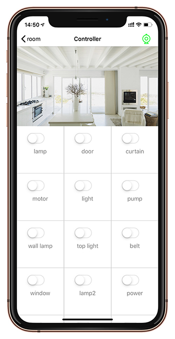
After adding the control box, we can realize the remote control of the light switch of the control box in the mobile phone app. When it comes to intelligence, we can not only use the mobile app to control the lights manually;
You can also customize the situational mode, such as one button to turn on / off all lights, or one button to turn on a specified number of lights, and turn off a specified number of lights at the same time;
In addition, you can customize the timing control operations, such as: Monday to Friday, 7:00 automatically turn on the bedroom lights. These flexibly defined scenario patterns, as well as a variety of trigger execution methods, have fully emerged intelligent portability and practicability.
For more detailed information about mobile phone app operation instructions, you can visit the Kincony official website to obtain.
- Switch Button Local Controlling
Through the manual button control mode is the simplest, no need of any third party equipment, direct finger press the key can, the first key corresponds to the first street lamp; the second key corresponds to the second street lamp, and so on. Fingers press the button, the light will open, press the button again, the light will be turned off.
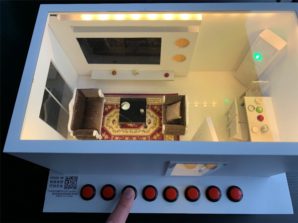
So far, we’ve used the KC868-H8 device to control the lightings, and we’ve learned to use solid-state relays for light power applications for the power expansion of lighting devices.
But if one KC868-H8 device doesn’t have enough control?
There are two solutions:
The first is to use multiple KC868-H8 devices, can be 2, 3, 4. Just plug in the device and wire the network;
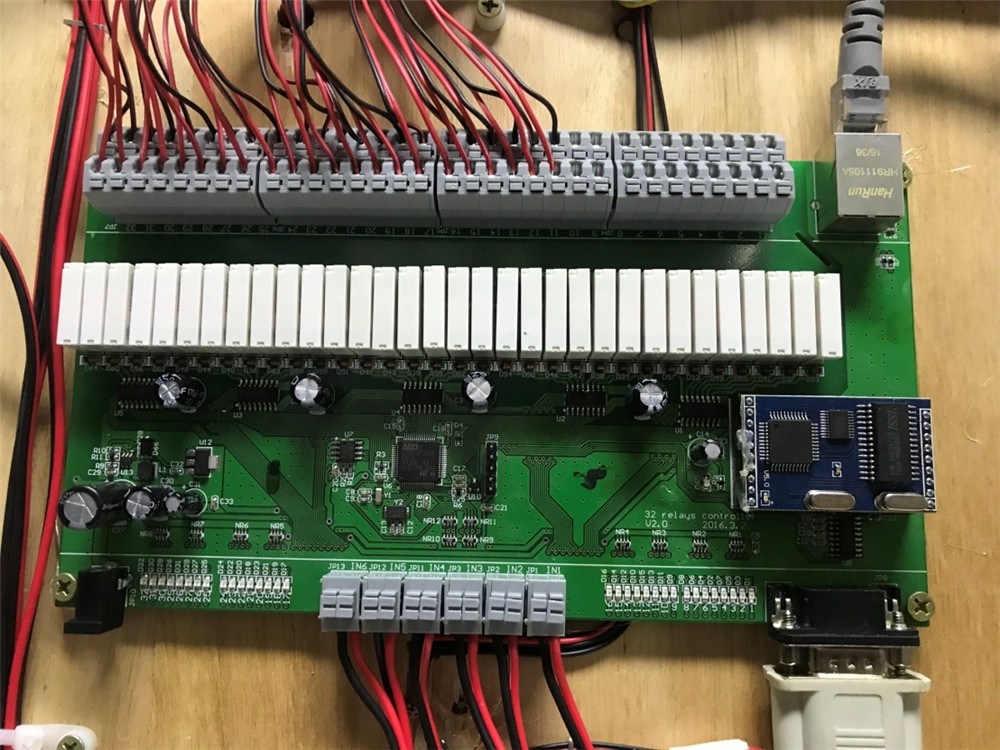
The second way is to use a 32-way KC868-H32 intelligent device.
For example: we just demonstrated the model of a single suite, when the number of paths to control the lights is more than 8, we can use the KC868-H32 device.
Let’s take a look at the KC868-H32 device for the villa model control example.
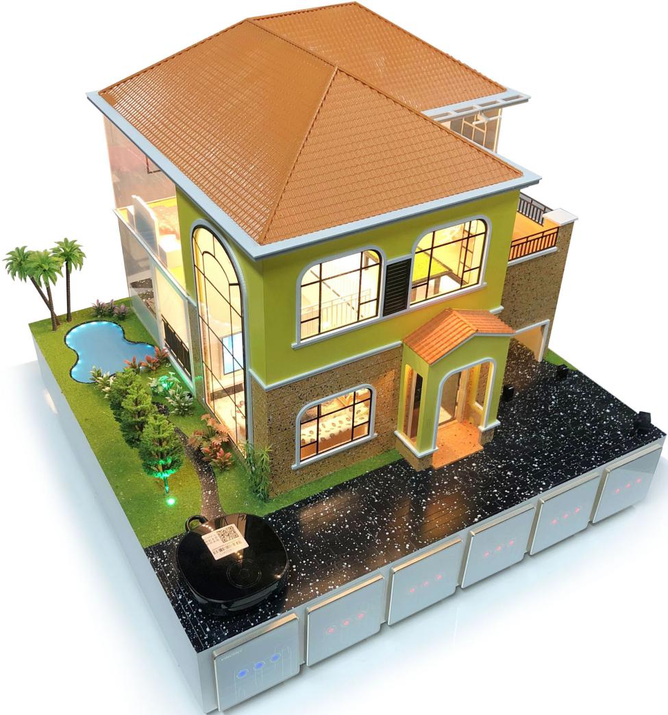
This is a light control scheme for a villa connected by KC868-H32
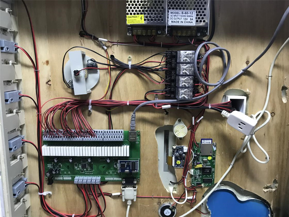
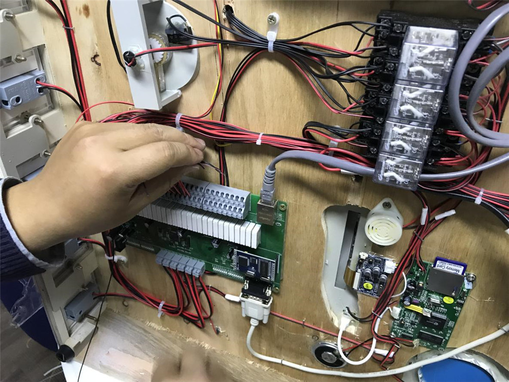
KC868-H32 connection to various control devices at the bottom of the villa model
The output end is connected to various light control devices, and the input end is connected to the manual control key button.
Above all is the lighting control smart system implementation case showing.
For more details information, you can find our official website with below link:


