Thank you, I think I have an idea of what's been making this hard to figure out.
I sniffed the traffic from the App to see this for resetting chip 1's data:
Code:
01 05 02 08 ff 00 0c 40
Which decodes to running a 0x05 operation on 520 with a value of 1. I am able to replicate this exact operation with this esphome switch:
Code:
switch:

  - platform: modbus_controller

    id: clear_btn_chip_1

    name: "Clear Energy, Chip 1"

    register_type: coil

    address: 520
And it does what you'd expect:
Code:
[02:18:32.380][V][switch:021]: 'Clear Energy, Chip 1' Turning ON.

[02:18:32.383][V][modbus_controller.switch:090]: write_state 'Clear Energy, Chip 1': new value = ON type = 1 address = 208 offset = 0

[02:18:32.387][V][modbus:1141]: Adding frame to tx queue: 1:05:02:08:FF:00

[02:18:32.391][V][modbus_controller:534]: Command queued 5 0x208 1

[02:18:32.394][V][switch:064]: 'Clear Energy, Chip 1' >> ON

[02:18:32.415][V][modbus:807]: Write: 01:05:02:08:FF:00:0C:40 20138ms after last send, 20118ms after last receive

[02:18:32.423][V][modbus:168]: Received first byte 1 (0X1) of 8 bytes 8ms after last send

[02:18:32.426][V][modbus_controller:391]: Command ACK 0x208 2303

[02:18:32.430][V][modbus:1217]: Clearing buffer of 8 bytes - parse succeeded 16ms after last send
This
DOES reset the kWh values.
Here's the catch, which is what has been throwing me:
reset only works ONCE per power cycle. If you gain more kWh data after the reset, you can not issue the command again to re-clear the data. You must power-cycle the device before issuing the command will work. I suspect something in the ARM firmware treats this coil like a one-time invocation and then never looks for the register to change again until the whole thing re-initialized.
It'd be great if it worked multiple times in a row.
---
With that mystery solved, what would cause watts to be reported negative? (NONE of the ct's are on devices which generate power. All of the CT's are installed in the exact same orientation (which side faces the breaker/source). It's possible that I've flipped some red/black wires on the pos/neg inputs on the CT pins, but..for this many?
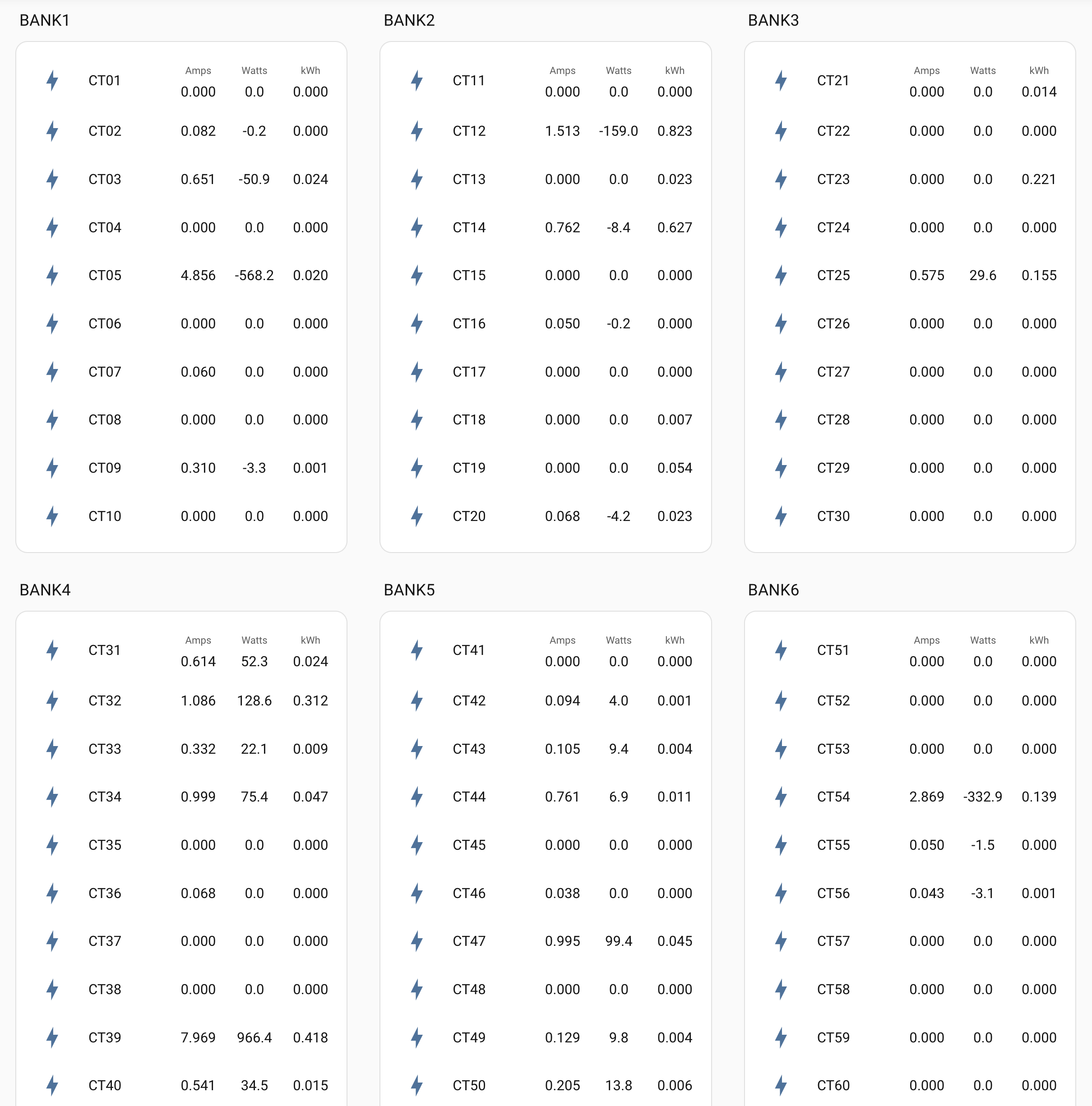
Well, I guess this works:
Code:
Additional configuration register:

- Register 30: Bidirectional CT mode (0x03 read, 0x06 write)

  - 0: Disabled

  - 1: Enabled
Turned that off... which "fixes" the problem, technically, but I feel like if I have it all wired up correctly I shouldn't be seeing negative watts.
Still want to fix it the "right" way.




