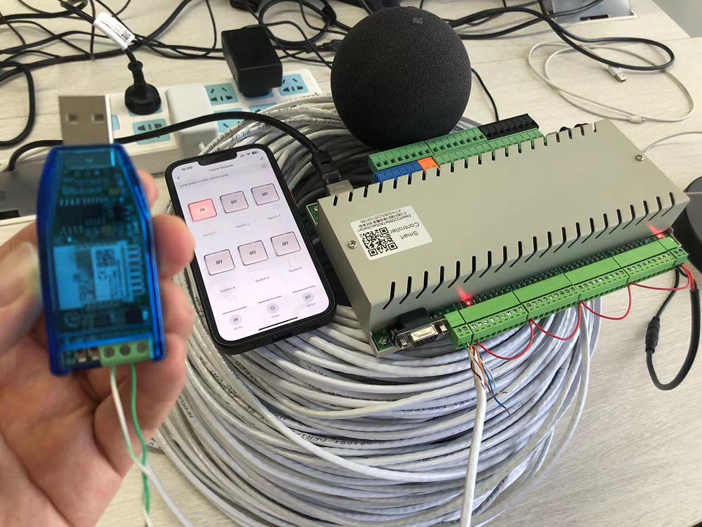
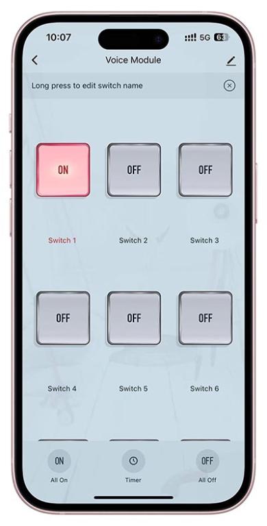
This is sample demo let RS485 digital output device (KinCony KC868-H32BS controller) can work with Tuya app by internet. you can let your own RS485 relay board add to Tuya app.
added Tuya adapter v2, relay board will support alexa or Google home speaker for voice control directly.


arduino source code download:
 Tuya_AdapterV2_RS485_Relay.zip (Size: 2.63 KB / Downloads: 477)
Code:
#include <ModbusMaster.h>

#include <Arduino.h>

#include <TuyaWifi.h>

#include "HardwareSerial.h"

//---------RS485 setting

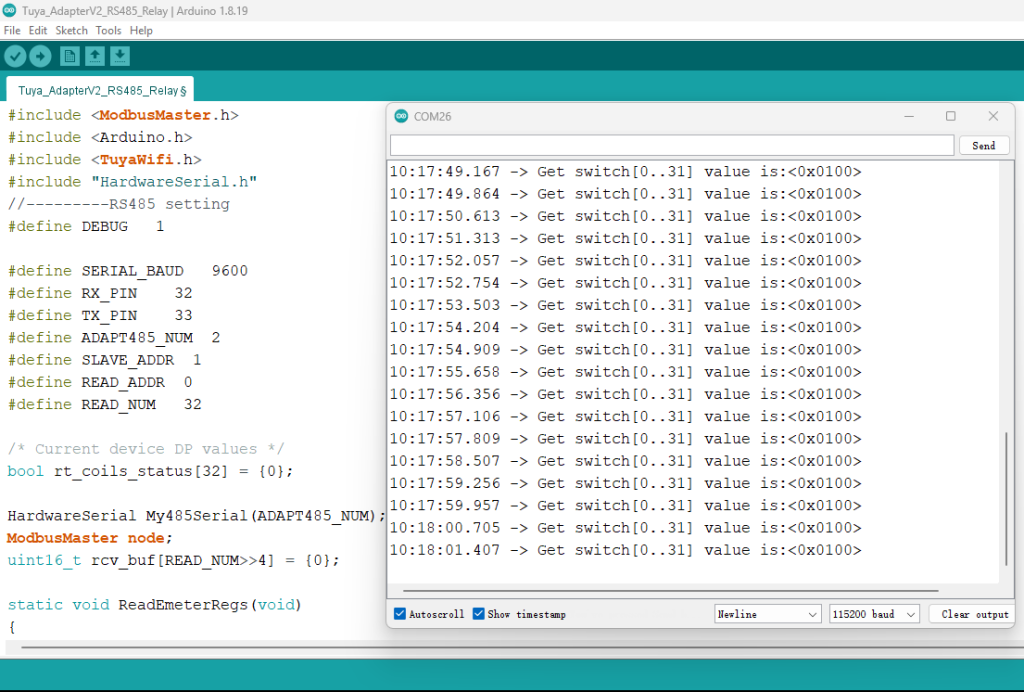
#define DEBUG   1


#define SERIAL_BAUD   9600

#define RX_PIN    32

#define TX_PIN    33

#define ADAPT485_NUM  2

#define SLAVE_ADDR  1

#define READ_ADDR  0

#define READ_NUM   32


/* Current device DP values */

bool rt_coils_status[32] = {0};


HardwareSerial My485Serial(ADAPT485_NUM);

ModbusMaster node;

uint16_t rcv_buf[READ_NUM>>4] = {0};


static void ReadEmeterRegs(void)

{

  uint32_t read_tmp = 0;


  uint8_t result = node.readCoils(READ_ADDR, READ_NUM);

  if (result == node.ku8MBSuccess) {//if communicate successful then


    for (uint8_t i = 0; i < 2; i++)

    {

      rcv_buf[i] = node.getResponseBuffer(i);

      for(uint8_t j = 0; j < 16; j++)

      {

        if(j<8) rt_coils_status[i*16 + j+8] = (rcv_buf[1-i]&(1<<j))?true:false;

        else rt_coils_status[i*16 + j - 8] = (rcv_buf[1-i]&(1<<j))?true:false;

      }

    }


    #if DEBUG

    Serial1.print("Get switch[0..31] value is");

    Serial1.print(":<0x");

    Serial1.print(rcv_buf[0],HEX);

    Serial1.print(rcv_buf[1],HEX);

    Serial1.println("> ");

    #endif


  }

  else

  {

    node.clearResponseBuffer();

  }


  delay(100);

}


//---RS485 setting end----


TuyaWifi my_device;


/* Current LED status */

unsigned char led_state = 0;

/* Connect network button pin */

int key_pin = 25;


/* Data point define */

typedef enum

{

  DPID_SWITCH01 = 1,

  DPID_SWITCH02,DPID_SWITCH03,

  DPID_SWITCH04,DPID_SWITCH05,DPID_SWITCH06,

  DPID_SWITCH07 = 113,

  DPID_SWITCH08,DPID_SWITCH09,DPID_SWITCH10,

  DPID_SWITCH11,DPID_SWITCH12,DPID_SWITCH13,

  DPID_SWITCH14,DPID_SWITCH15,DPID_SWITCH16,

  DPID_SWITCH17,DPID_SWITCH18,DPID_SWITCH19,

  DPID_SWITCH20,DPID_SWITCH21,DPID_SWITCH22,

  DPID_SWITCH23,DPID_SWITCH24,DPID_SWITCH25,

  DPID_SWITCH26,DPID_SWITCH27,DPID_SWITCH28,

  DPID_SWITCH29,DPID_SWITCH30,DPID_SWITCH31,

  DPID_SWITCH32,

}H32BS_DPID_DEF;


/*const unsigned char dpid_arr[32] = {

  1,2,3,4,5,6,

  113,114,115,116,117,118,119,120,

  121,122,123,124,125,126,127,128,

  129,130,131,132,133,134,135,136,

  137,138,

};*/


#define LED_WiFi  26

//#define LED_User  33


/* Stores all DPs and their types. PS: array[][0]:dpid, array[][1]:dp type.

 *                                     dp type(TuyaDefs.h) : DP_TYPE_RAW, DP_TYPE_BOOL, DP_TYPE_VALUE, DP_TYPE_STRING, DP_TYPE_ENUM, DP_TYPE_BITMAP

*/

unsigned char dp_array[][2] =

{

  {DPID_SWITCH01, DP_TYPE_BOOL},{DPID_SWITCH02, DP_TYPE_BOOL},

  {DPID_SWITCH03, DP_TYPE_BOOL},{DPID_SWITCH04, DP_TYPE_BOOL},

  {DPID_SWITCH05, DP_TYPE_BOOL},{DPID_SWITCH06, DP_TYPE_BOOL},

  {DPID_SWITCH07, DP_TYPE_BOOL},{DPID_SWITCH08, DP_TYPE_BOOL},


  {DPID_SWITCH09, DP_TYPE_BOOL},{DPID_SWITCH10, DP_TYPE_BOOL},

  {DPID_SWITCH11, DP_TYPE_BOOL},{DPID_SWITCH12, DP_TYPE_BOOL},

  {DPID_SWITCH13, DP_TYPE_BOOL},{DPID_SWITCH14, DP_TYPE_BOOL},

  {DPID_SWITCH15, DP_TYPE_BOOL},{DPID_SWITCH16, DP_TYPE_BOOL},


  {DPID_SWITCH17, DP_TYPE_BOOL},{DPID_SWITCH18, DP_TYPE_BOOL},

  {DPID_SWITCH19, DP_TYPE_BOOL},{DPID_SWITCH20, DP_TYPE_BOOL},

  {DPID_SWITCH21, DP_TYPE_BOOL},{DPID_SWITCH22, DP_TYPE_BOOL},

  {DPID_SWITCH23, DP_TYPE_BOOL},{DPID_SWITCH24, DP_TYPE_BOOL},


  {DPID_SWITCH25, DP_TYPE_BOOL},{DPID_SWITCH26, DP_TYPE_BOOL},

  {DPID_SWITCH27, DP_TYPE_BOOL},{DPID_SWITCH28, DP_TYPE_BOOL},

  {DPID_SWITCH29, DP_TYPE_BOOL},{DPID_SWITCH30, DP_TYPE_BOOL},

  {DPID_SWITCH31, DP_TYPE_BOOL},{DPID_SWITCH32, DP_TYPE_BOOL},

};


unsigned char pid[] = {"3ocztklfu3q32jab"}; ////change pid here....

unsigned char mcu_ver[] = {"1.0.0"};


/* last time */

unsigned long last_time = 0;


/**

 * @description: DP download callback function.

 * @param {unsigned char} dpid

 * @param {const unsigned char} value

 * @param {unsigned short} length

 * @return {unsigned char}

 */

unsigned char dp_process(unsigned char dpid,const unsigned char value[], unsigned short length)

{

  int16_t index_out_coil = -1;

  unsigned char get_down_cmd = false;


  for(int16_t i=0;i<32;i++)

  {

    if(dpid == dp_array[i][0])

    {

      index_out_coil = i;

      break;

    }

  }

  if(index_out_coil < 0) return TY_ERROR;


  get_down_cmd = my_device.mcu_get_dp_download_data(dpid,value,length);


  Serial1.print("Rcv Command:<dpid,");

  Serial1.print(dpid,DEC);

  Serial1.print(" value,");

  Serial1.print(value[0],HEX);

  Serial1.print(" len,");

  Serial1.println(length,HEX);

  Serial1.println("> ");


  #if DEBUG

    Serial1.print("get_down_cmd value is:<");

    Serial1.print(get_down_cmd,DEC);

    Serial1.println("> ");

    Serial1.print("Node WriteCoilAddr<");

    Serial1.print(index_out_coil,DEC);

    Serial1.print("> ");

  #endif


  delay(100);

  uint8_t result = node.writeSingleCoil(index_out_coil, value[0]);

  #if DEBUG

    Serial1.print(" result:<");

    Serial1.print(result,DEC);

    Serial1.println("> ");

  #endif


  delay(100);

  my_device.mcu_dp_update(dpid, value, length);

  return TY_SUCCESS;

}


void setup()

{


  My485Serial.begin(SERIAL_BAUD, SERIAL_8N1, RX_PIN, TX_PIN); //RS485 serial port

  node.begin(SLAVE_ADDR,My485Serial);

  Serial.begin(9600,SERIAL_8N1,22,19);  //Tuya module serial port

  Serial1.begin(115200,SERIAL_8N1,3,1);   //USB serial port


  // Serial with tuyawifi


  //Initialize led port, turn off led.

  pinMode(LED_WiFi, OUTPUT);

  digitalWrite(LED_WiFi, LOW);


/*  pinMode(LED_User, OUTPUT);

  digitalWrite(LED_User, LOW);*/


  //Initialize networking keys.

  pinMode(key_pin, INPUT_PULLUP);


  //Enter the PID and MCU software version

  my_device.init(pid, mcu_ver);

  //incoming all DPs and their types array, DP numbers

  my_device.set_dp_cmd_total(dp_array, 2);

  //register DP download processing callback function

  my_device.dp_process_func_register(dp_process);

  //register upload all DP callback function

  my_device.dp_update_all_func_register(dp_update_all);


  //delay(300);

  last_time = millis();

}


void loop()

{

  ReadEmeterRegs();  // read RS485 sensor

  my_device.uart_service();


  //Enter the connection network mode when Pin7 is pressed.

  if (digitalRead(key_pin) == LOW) {

    delay(80);

    if (digitalRead(key_pin) == LOW) {

      my_device.mcu_set_wifi_mode(SMART_CONFIG);

    }

  }

  /* LED blinks when network is being connected */

  if ((my_device.mcu_get_wifi_work_state() != WIFI_LOW_POWER) && (my_device.mcu_get_wifi_work_state() != WIFI_CONN_CLOUD) && (my_device.mcu_get_wifi_work_state() != WIFI_SATE_UNKNOW)) {

    if (millis()- last_time >= 500) {

      last_time = millis();


      if (led_state == LOW) {

        led_state = HIGH;

      } else {

        led_state = LOW;

      }

      digitalWrite(LED_WiFi, led_state);

    }

  }


  /* report the temperature and humidity */

  if ((my_device.mcu_get_wifi_work_state() == WIFI_CONNECTED) ||

      (my_device.mcu_get_wifi_work_state() == WIFI_CONN_CLOUD)) {

    dp_update_all();

  }


  delay(500);

}


static bool coils_old_status[32] = {false};


unsigned char tmp_cmd = 0;

static void CompareAndReport(void)

{

  for(int16_t i=0;i<32;i++)

  {

    if(coils_old_status[i] != rt_coils_status[i])

    {

      coils_old_status[i] = rt_coils_status[i];

      tmp_cmd = rt_coils_status[i]?1:0;

      #if 0

      Serial1.print("Changed happed:<dpid,");

      Serial1.print(dp_array[i][0],DEC);

      Serial1.println("> ");

      #endif

      my_device.mcu_dp_update(dp_array[i][0],tmp_cmd, 1);

      delay(10);

      //break;

    }

  }

}

/**

 * @description: Upload all DP status of the current device.

 * @param {*}

 * @return {*}

 */

void dp_update_all(void)

{

  CompareAndReport();


}


