Welcome, Guest
You have to register before you can post on our site.

Username
  

Password


Search Forums

(Advanced Search)

Forum Statistics
» Members: 10,447
» Latest member: bhushan1301
» Forum threads: 4,326
» Forum posts: 21,312

Full Statistics

Online Users
There are currently 361 online users.
» 0 Member(s) | 345 Guest(s)
AhrefsBot, Applebot, Baidu, Bytespider, Crawl, Google, PetalBot, bot

Latest Threads
kc868-a6 analog input
Forum: KC868-A6
Last Post: admin
Yesterday, 09:56 AM
» Replies: 3
» Views: 396
F24 ESPHome yaml for home...
Forum: F24
Last Post: admin
Yesterday, 07:25 AM
» Replies: 0
» Views: 10
[arduino code examples fo...
Forum: F24
Last Post: admin
Yesterday, 05:35 AM
» Replies: 0
» Views: 13
[arduino code examples fo...
Forum: F24
Last Post: admin
Yesterday, 05:33 AM
» Replies: 0
» Views: 13
[Arduino source code for ...
Forum: KC868-A2
Last Post: admin
Yesterday, 05:31 AM
» Replies: 6
» Views: 1,752
KC868-A4 – Relay 1 clicks...
Forum: KC868-A series and Uair Smart Controller
Last Post: admin
11-03-2026, 11:58 PM
» Replies: 3
» Views: 51
⚡ 40 Buttons, 36 Lighting...
Forum: DIY Project
Last Post: lulu01
11-03-2026, 07:34 PM
» Replies: 24
» Views: 3,047
[arduino code examples fo...
Forum: CO16
Last Post: admin
11-03-2026, 03:04 AM
» Replies: 0
» Views: 23
[arduino code examples fo...
Forum: CO16
Last Post: admin
11-03-2026, 01:34 AM
» Replies: 0
» Views: 26
[arduino code examples fo...
Forum: CO16
Last Post: admin
11-03-2026, 12:15 AM
» Replies: 0
» Views: 27

  [arduino code examples for F32]-03 Read analog input ports value
Posted by: admin - 11-28-2024, 11:43 AM - Forum: F32 - No Replies

Code:
/*
* Made by KinCony IoT: https://www.kincony.com
*
* Description:
* This Arduino program reads analog values from four analog input pins (A1, A2, A3, A4)
* and prints the values to the Serial Monitor. The analog inputs are defined with specific
* GPIO pins and the program reads the voltage levels from these pins every 2 seconds.
*
* Pin Definitions:
* - A1: GPIO 5
* - A2: GPIO 7
* - A3: GPIO 6
* - A4: GPIO 4
*/

#define ANALOG_A1   5   // Define GPIO pin for analog input A1
#define ANALOG_A2   7   // Define GPIO pin for analog input A2
#define ANALOG_A3   6   // Define GPIO pin for analog input A3
#define ANALOG_A4   4   // Define GPIO pin for analog input A4

void setup()
{
    Serial.begin(115200); // Initialize serial communication at 115200 baud rate
    delay(500); // Short delay to allow serial communication to start

    pinMode(ANALOG_A1, INPUT); // Set GPIO 5 as an input for analog signal A1
    pinMode(ANALOG_A2, INPUT); // Set GPIO 7 as an input for analog signal A2
    pinMode(ANALOG_A3, INPUT); // Set GPIO 6 as an input for analog signal A3
    pinMode(ANALOG_A4, INPUT); // Set GPIO 4 as an input for analog signal A4
}

void loop()
{
    // Read and print analog values from the defined pins
    Serial.print("A1=");
    Serial.println(analogRead(ANALOG_A1)); // Read and print the value from A1
    Serial.print("A2=");
    Serial.println(analogRead(ANALOG_A2)); // Read and print the value from A2
    Serial.print("A3=");
    Serial.println(analogRead(ANALOG_A3)); // Read and print the value from A3
    Serial.print("A4=");
    Serial.println(analogRead(ANALOG_A4)); // Read and print the value from A4
   
    delay(2000); // Wait for 2 seconds before the next reading
}
arduino ino file download: 

.zip   3-analog-input.zip (Size: 769 bytes / Downloads: 771)

Print this item

  [arduino code examples for F24]-02 Read digital input ports state by PCF8575 chip
Posted by: admin - 11-28-2024, 11:41 AM - Forum: F24 - No Replies

Code:
/*
* Made by KinCony IoT: https://www.kincony.com
*
* Description:
* This Arduino program reads the state of two 16-channel PCF8575 I/O expanders
* and prints the state of all input pins (1-24) to the Serial Monitor. The state of
* each pin is represented as a bit in a 24-bit value, where each bit corresponds
* to an input pin. The program prints the input state in binary format.
*
* Pin Definitions:
* - SDA: GPIO 8
* - SCL: GPIO 18
* - PCF8575 I2C Address: 0x24 for inputs 1-16, 0x26 for inputs 17-24
*/

#include "Arduino.h"
#include "PCF8575.h"

// Define I2C pins
#define I2C_SDA 8  // Define SDA pin
#define I2C_SCL 18  // Define SCL pin

// Set I2C addresses
PCF8575 pcf8575_IN1(0x24); // The I2C address of the first PCF8575 (inputs 1-16)
PCF8575 pcf8575_IN2(0x26); // The I2C address of the second PCF8575 (inputs 17-24)

void setup() {
    Serial.begin(115200);

    // Initialize I2C communication
    Wire.begin(I2C_SDA, I2C_SCL); // Initialize I2C with defined SDA and SCL pins

    // Initialize both PCF8575 modules
    pcf8575_IN1.begin();
    pcf8575_IN2.begin();

    Serial.println("KinCony F24 24 channel input state 0:ON  1:OFF");
}

void loop() {
    uint32_t state = 0; // Use a 32-bit variable to store the state of all 24 pins

    // Read the state of each pin from the first PCF8575 (inputs 1-16)
    for (int pin = 0; pin < 16; pin++) {
        if (pcf8575_IN1.read(pin)) {
            state |= (1UL << pin); // Set the bit for the active pin (inputs 1-16)
        }
    }

    // Read the state of each pin from the second PCF8575 (inputs 17-24, corresponding to pins 0-7)
    for (int pin = 0; pin < 8; pin++) {
        if (pcf8575_IN2.read(pin)) {
            state |= (1UL << (pin + 16)); // Set the bit for the active pin (inputs 17-24)
        }
    }

    // Print the state of all 24 inputs in binary format
    Serial.print("Input state: ");
    Serial.println(state, BIN); // Print the state of inputs in binary

    delay(500); // Delay 500ms
}
arduino ino file download:

.zip   2-digital-input.zip (Size: 976 bytes / Downloads: 738)

Print this item

  [arduino code examples for F24]-01 Turn ON/OFF relay by PCF8575 chip
Posted by: admin - 11-28-2024, 11:40 AM - Forum: F24 - No Replies

Code:
/*
* Made by KinCony IoT: https://www.kincony.com
*
* This program controls a 24-channel relay board via two PCF8575 I/O expanders.
* It sequentially turns on each relay and then turns them off in a loop.
*
* Pin Definitions:
* - SDA: GPIO 8
* - SCL: GPIO 18
*
* Delay Time:
* - 200 milliseconds between switching relays
*/

#include <Wire.h>        // Include the Wire library for I2C communication
#include <PCF8575.h>     // Include the PCF8575 library to control the I/O expander

#define SDA 8            // Define the SDA pin
#define SCL 18           // Define the SCL pin
#define DELAY_TIME 200   // Define the delay time in milliseconds

// Set I2C addresses of the PCF8575 modules
#define I2C_ADDRESS_R1 0x25 // I2C address of the first PCF8575 module
#define I2C_ADDRESS_R2 0x26 // I2C address of the second PCF8575 module

PCF8575 pcf8575_R1(I2C_ADDRESS_R1); // Create a PCF8575 object for the first module (for relays 9-24)
PCF8575 pcf8575_R2(I2C_ADDRESS_R2); // Create a PCF8575 object for the second module (for relays 1-8)

void setup() {
  // Initialize I2C communication
  Wire.begin(SDA, SCL); // SDA on GPIO 8, SCL on GPIO 18 (according to your board's configuration)
 
  // Initialize serial communication for debugging (optional)
  Serial.begin(115200);
  Serial.println("PCF8575 Relay Control: Starting...");

  // Initialize the PCF8575 modules
  pcf8575_R1.begin();
  pcf8575_R2.begin();

  // Turn off all relays initially (set all pins HIGH)
  for (int i = 0; i < 16; i++) {
    pcf8575_R1.write(i, HIGH); // Set relays 9-24 to OFF (assuming HIGH means OFF for relays)
    pcf8575_R2.write(i, HIGH); // Set relays 1-8 to OFF (assuming HIGH means OFF for relays)
  }
}

void loop() {
  // Sequentially turn on each relay (1-24)
 
  // First control the relays on the second PCF8575 (relays 1-8, corresponding to pins 8-15)
  for (int i = 8; i < 16; i++) {
    pcf8575_R2.write(i, LOW);   // Turn on the relay at pin i (LOW means ON for the relay)
    delay(DELAY_TIME);          // Wait for DELAY_TIME milliseconds
  }

  // Then control the relays on the first PCF8575 (relays 9-24)
  for (int i = 0; i < 16; i++) {
    pcf8575_R1.write(i, LOW);   // Turn on the relay at pin i (LOW means ON for the relay)
    delay(DELAY_TIME);          // Wait for DELAY_TIME milliseconds
  }

  // Sequentially turn off each relay (1-24)
 
  // First control the relays on the second PCF8575 (relays 1-8, corresponding to pins 8-15)
  for (int i = 8; i < 16; i++) {
    pcf8575_R2.write(i, HIGH);  // Turn off the relay at pin i (HIGH means OFF for the relay)
    delay(DELAY_TIME);          // Wait for DELAY_TIME milliseconds
  }

  // Then control the relays on the first PCF8575 (relays 9-24)
  for (int i = 0; i < 16; i++) {
    pcf8575_R1.write(i, HIGH);  // Turn off the relay at pin i (HIGH means OFF for the relay)
    delay(DELAY_TIME);          // Wait for DELAY_TIME milliseconds
  }
}
arduino ino file download:

.zip   1-relay.zip (Size: 1.03 KB / Downloads: 756)

Print this item

  F24 ESP32-S3 IO pins define
Posted by: admin - 11-28-2024, 11:39 AM - Forum: F24 - Replies (2)

ANALOG_A1(0-5v)    GPIO5
ANALOG_A2(0-5v)    GPIO7
ANALOG_A3(4-20mA)  GPIO6
ANALOG_A4(4-20mA)  GPIO4

IIC SDA:GPIO8
IIC SCL:GPIO18

PCF8575/XL9555:U27 (relay9-24) i2c address: 0x25
PCF8575/XL9555:U23 (DI1-16) i2c address: 0x24
PCF8575/XL9555:U49 i2c address:  0x26
  PCF8575/XL9555(pin number0-7) : DI17-24
  PCF8575/XL9555(pin number8-11) :relay5-8
  PCF8575/XL9555(pin number12-15) :relay1-4

Note: after 2026-11-01 KinCony begin use XL9555 i2c extend chip. you can use KCS v3 "SYSTEM" webpage to scan device show the model or config by ESPHome to scan i2c bus, will find the chip model.


if config by ESPHome:

relay1: pcf8575(U49) number:12
relay2: pcf8575(U49) number:13
relay3: pcf8575(U49) number:14
relay4: pcf8575(U49) number:15
relay5: pcf8575(U49) number:8
relay6: pcf8575(U49) number:9
relay7: pcf8575(U49) number:10
relay8: pcf8575(U49) number:11

RF433MHz wireless receiver: GPIO40
------------------------

Ethernet (W5500) I/O define:

clk_pin: GPIO42
mosi_pin: GPIO43
miso_pin: GPIO44
cs_pin: GPIO41

interrupt_pin: GPIO2
reset_pin: GPIO1

--------------------
RS485:
RXD:GPIO17
TXD:GPIO16
--------------------
Tuya module:
RXD:GPIO38
TXD:GPIO39

Tuya network button: Tuya module's P28
Tuya network LED: Tuya module's P16

---------------------
1-wire (pull-up resistance on PCB):
1-wire1:GPIO48
1-wire2:GPIO47
1-wire3:GPIO21
1-wire4:GPIO15

1-wire (without resistance on PCB):
1-wire1:GPIO13
1-wire2:GPIO14
------------------------
SD Card:
SPI-MOSI:GPIO10
SPI-SCK:GPIO11
SPI-MISO:GPIO12
SPI-CS:GPIO9
------------------------
24C02 EPROM i2c address: 0x50
DS3231 RTC i2c address: 0x68
SSD1306 display: i2c address:0x3c

Print this item

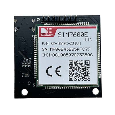
  KinCony SIM7600E-L1C 4G breakout LTE core module released
Posted by: admin - 11-28-2024, 11:33 AM - Forum: News - No Replies

The SIM7600E-L1C is a versatile and cost-effective 4G LTE module that integrates multiple communication functionalities, making it suitable for a wide range of IoT and M2M applications. Developed by KinCony, this module provides robust connectivity and high-speed data transmission capabilities, ensuring seamless integration into IoT ecosystems.
[Image: sim7600-1_pix400.jpg][Image: sim7600-2_pix400.jpg]
[Image: sim7600-key-parts.png]
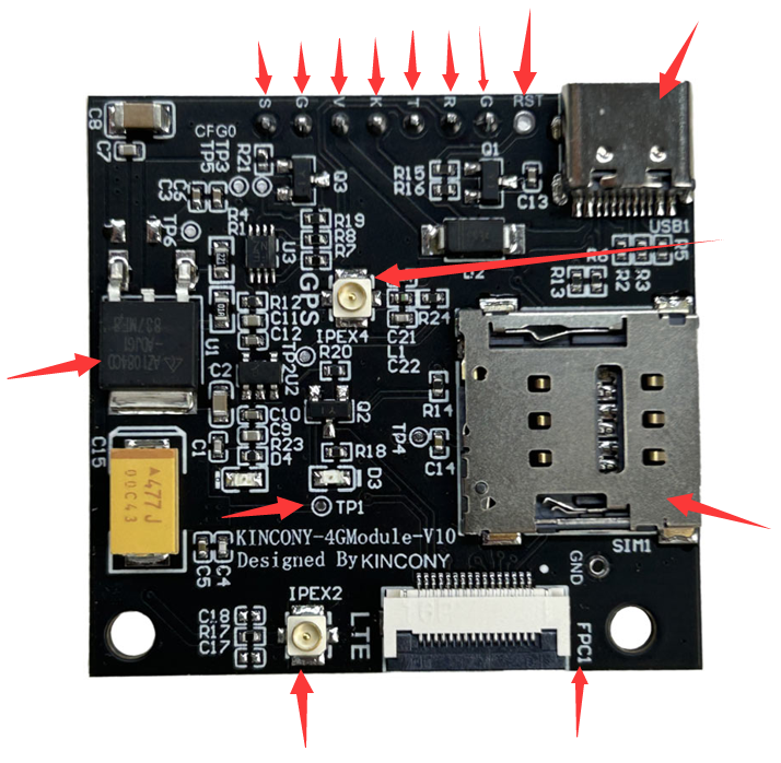
USB-C: connect with SIM7600E's USB port , debug by AT command
pin-S (SLEEP): set module to SLEEP mode
pin-G (GROUND): GND
pin-V (VCC): power supply DC 5-10V
pin-K (KEY): power on/off module
pin-T (TXD): send data
pin-R (RXD): receive data
pin-G (GROUND): GND
pin-RST: SIM7600 chip RESET pin
power chip: AZ1084CD
IPEX2: 4G antenna
IPEX4: GPS antenna
SIM card: Drawer SIM card holder (NANO)
TP1: DC4V power test point
SIM7600 network LED indicator: if blink means network registration successful
1: LED always ON: Searching network/call connect
2: LED 200ms ON, 200ms OFF: Data transmit
3: LED 800ms ON, 800ms OFF: Registered network
4: LED OFF: power off/Sleep
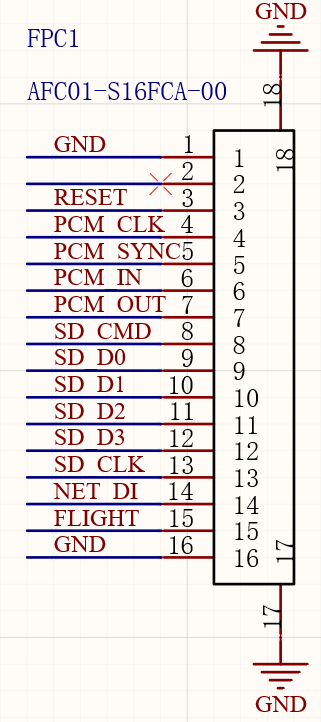
FPC1(16 pins) extender pins define:
[Image: sim7600-fpc.png]
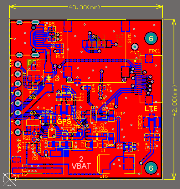
[Image: sim7600-pcb.png]

Print this item

  GPIO Connector
Posted by: williemcvillage - 11-28-2024, 09:14 AM - Forum: KC868-AM - Replies (2)

Hi, I recently bought this board KC868-AM, and I want to use the free GPIOs onboard. 

Can you recommend a connector to soldier on the board? Maybe an aliexpress link?

Thanks

Print this item

  Configure presence sensor settings in ESPHome
Posted by: johnsmith8439 - 11-28-2024, 04:25 AM - Forum: KC868-A16 - Replies (5)

Hello, can I configure settings for your presence sensor in esphome:
https://www.aliexpress.com/item/1005006030673158.html
Or should I configure using remote?
Also, which presence sensor component does it use? LD2410? Thank you.

Print this item

Information IR Receiver Compatibility with KC868-A6 and KC868-A16
Posted by: BHD-13 - 11-28-2024, 12:05 AM - Forum: KC868-A series and Uair Smart Controller - Replies (1)

Hi Admin,
I came across your lesson about ''How to decode IR signal by ESPHome'' which i found extremely helpful and straightforward.
https://www.kincony.com/forum/showthread.php?tid=1220

I want to know whether it is possible to use an IR receiver like the VS1838B on the KC868-A6 or the KC868-16 and if possible, how to wire it.
[Image: Sf60acd7594324052b198ef4d9593c41fS.jpg_1....jpg_.webp]

Print this item

Information IR Receiver Compatibility with KC868-A6 and KC868-A16
Posted by: BHD-13 - 11-27-2024, 11:52 PM - Forum: KC868-A series and Uair Smart Controller - Replies (1)

Hi Admin,
I came across your lesson about ''How to decode IR signal by ESPHome'' which i found extremely helpful and straightforward.
https://www.kincony.com/forum/showthread.php?tid=1220

I want to know whether it is possible to use an IR receiver like the VS1838B on the KC868-A6 or the KC868-16 and if possible, how to wire it.
[Image: Sf60acd7594324052b198ef4d9593c41fS.jpg_1....jpg_.webp]

Print this item

  Suitable CT clamps for M30
Posted by: sumnerboy - 11-27-2024, 08:33 PM - Forum: KC868-M16 / M1 / MB / M30 - Replies (23)

Hi,

I am very interested in getting an M30 for monitoring the various circuits in my home. Some circuits only draw a 1-2A, some 8-10A, some 20-24A.

Can you please provide a list of suitable CT clamps that will work with the M30 for a various range of currents?

Ideally model numbers and specifications so we can source them directly if required.

Many thanks,
Ben

Print this item